Control apparatus for a vehicular alternator

a control apparatus and vehicular alternator technology, applied in the direction of electric generator control, dynamo-electric converter control, generator control by field variation, etc., can solve the problems of increasing the number of components, increasing the cost of control apparatus, and increasing the complexity of control apparatus, so as to reduce the cost, improve reliability, and attenuate the field current

Active Publication Date: 2007-11-20
MITSUBISHI ELECTRIC CORP
View PDF7 Cites 24 Cited by
  • Summary
  • Abstract
  • Description
  • Claims
  • Application Information

AI Technical Summary

Benefits of technology

[0008]Accordingly, the present invention is intended to solve the various problems as referred to above, and has for its object to obtain a control apparatus for a vehicular alternator which is capable of achieving improvement in reliability and reduction in cost by making it possible to attenuate a field current of a rotor coil with the use of a simple circuit.
[0010]According to the present invention, it is possible to attenuate the field current of the rotor coil with a simple circuit, whereby the reliability of the control apparatus can be improved, and the cost of manufacture thereof can be reduced.

Problems solved by technology

In such a known control apparatus for a vehicular alternator, a first attenuating circuit and a second non-attenuating circuit are switched over from one to the other by the use of two switches, thus resulting in a problem that the structure of the control apparatus becomes complicated and expensive.
In addition, since the first and second circuits have diodes, respectively, there is another problem that the number of component parts is increased, thereby making the control apparatus further expensive.
Moreover, if the two switches are turned off at the same time, there will be a possibility that the control apparatus might be destroyed by an overvoltage, so there is a further problem that an additional circuit is required so as to avoid this, thus making the structure of the control apparatus further complicated.

Method used


Image

  • Control apparatus for a vehicular alternator
  • Control apparatus for a vehicular alternator

Examples


embodiment 1

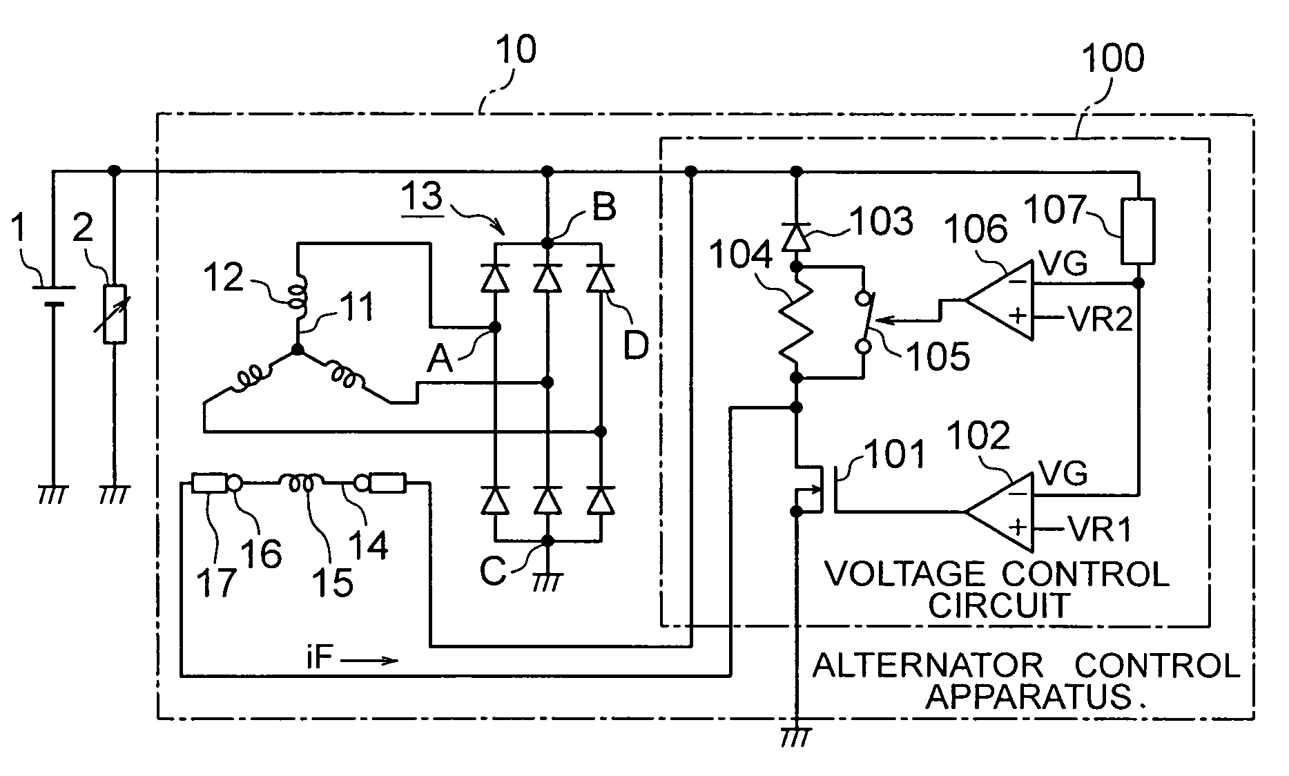
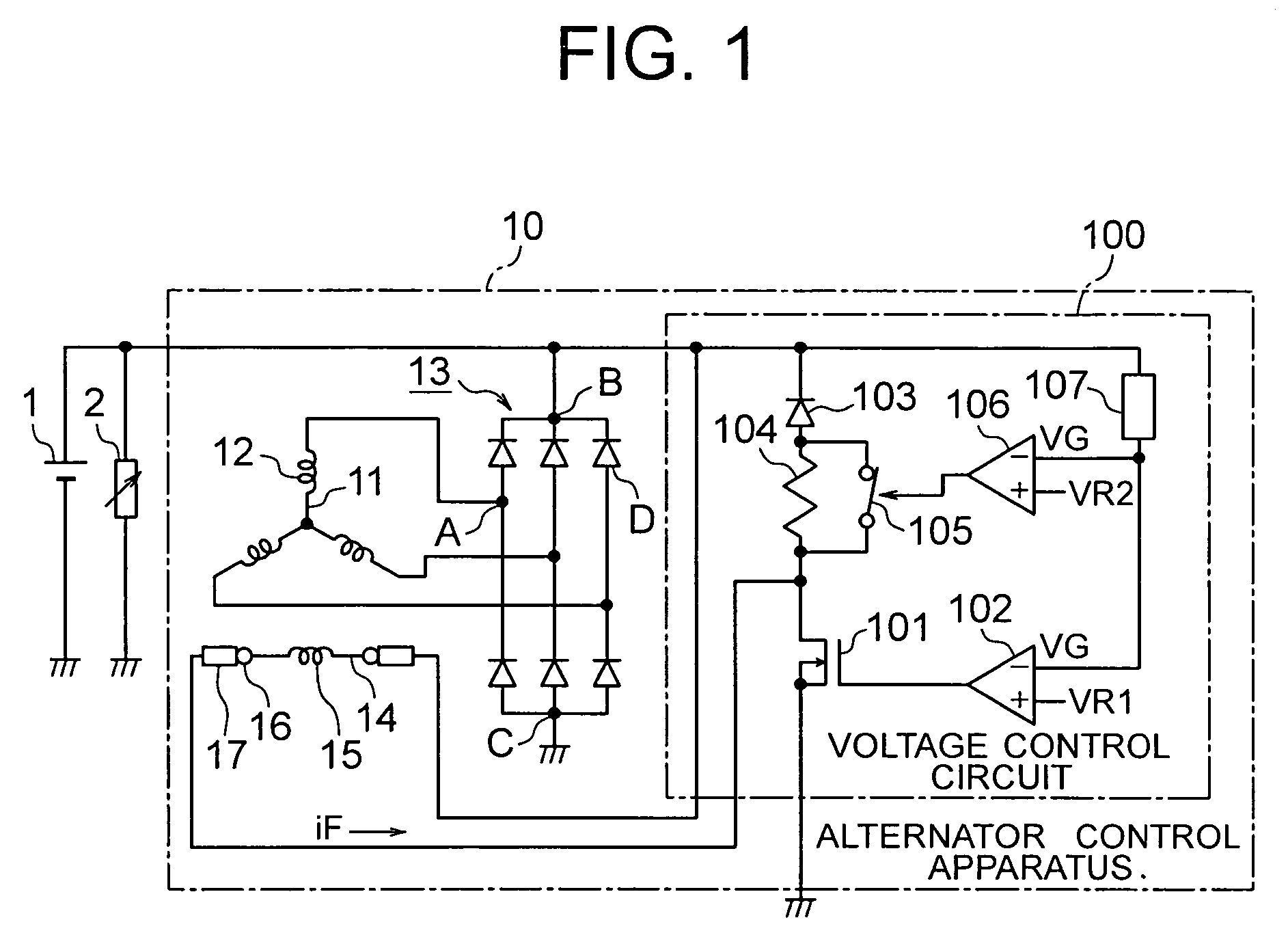
[0014]FIG. 1 is a circuit diagram that conceptually shows a control apparatus for a vehicular alternator according to a first embodiment of the present invention.

[0015]In FIG. 1, the control apparatus for a vehicular alternator (hereinafter also referred to as an alternator control apparatus), generally designated at reference numeral 10, is connected to an on-board or vehicle-mounted battery 1. An electric load 2 comprising a variety of kinds of on-board devices is connected to the battery 1. The alternator control apparatus 10 serves to control a voltage (hereinafter referred to as a power generation voltage) generated by the alternator in accordance with the electric load 2 that varies by turning on / off of each on-board device.

[0016]The alternator control apparatus 10 includes an three-phase armature coil 12 wound around a stator core 11, a rectifier circuit 13 connected to the armature coil 12, a rotor 14 arranged in a manner to be rotatable relative to the armature coil 12, a r...


PUM


Abstract

A control apparatus for a vehicular alternator can improve its reliability and reduce its cost by attenuating a field current of a rotor coil with a simple circuit. The apparatus includes an armature coil, a rectifier circuit, a rotor coil and a voltage control circuit. The rectifier circuit has an AC input terminal, a positive and a negative output terminal. The voltage control circuit controls a generation voltage to be substantially constant by interrupting a field current when a generation voltage exceeds a first predetermined voltage, while passing the field current when the generation voltage is equal to or lower than the first predetermined voltage. A circulation circuit comprising a diode and a current attenuation element serves to circulate the field current upon interruption thereof. A short-circuiting circuit short-circuits the current attenuation element. A short-circuit control circuit opens the short-circuiting circuit when the generation voltage exceeds a second predetermined voltage.

Description

BACKGROUND OF THE INVENTION[0001]1. Field of the Invention[0002]The present invention relates to a control apparatus for a vehicular alternator, and more particularly, to a new technique for achieving improved reliability and cost reduction.[0003]2. Description of the Related Art[0004]A known control apparatus for a vehicular alternator operates to switch the alternator so as to be connected to a circuit that consumes energy due to a field current, by the use of a resistor, a diode, etc., in order to quickly reduce the field current (see, for example, a first patent document (Japanese patent application laid-open No. 2003-174799)).[0005]In such a known control apparatus for a vehicular alternator, a first attenuating circuit and a second non-attenuating circuit are switched over from one to the other by the use of two switches, thus resulting in a problem that the structure of the control apparatus becomes complicated and expensive.[0006]In addition, since the first and second circu...

Claims


Application Information

Patent Timeline
Patent Type & Authority Patents(United States)
IPC IPC(8): H02P9/14
CPCH02P9/30H02P9/48H02J7/18H02J7/14
Inventor NISHIMURA, SHINJIMIYAJI, WAKAKI
Owner MITSUBISHI ELECTRIC CORP
Why Eureka
Try Eureka