Aerosol mobility size spectrometer

a technology of mobility size and aerosol, which is applied in the direction of measurement devices, instruments, material analysis, etc., can solve the problems of high inhomogeneous spatial and temporal distribution of atmospheric aerosol, inability to understand ambient aerosol properties, and often compromised aircraft-base measurements, so as to improve the ability to study and improve time resolution

Active Publication Date: 2007-11-20
BROOKHAVEN SCI ASSOCS
View PDF2 Cites 20 Cited by
  • Summary
  • Abstract
  • Description
  • Claims
  • Application Information

AI Technical Summary

Benefits of technology

[0012]Additionally, the device further preferably includes a means for saturating and growing the aerosol particles through a condensation process to facilitate detecting the particles. In this regard, the housing preferably includes a growth section having a thermoelectric cooler disposed downstream of the separation section for increasing the size of saturated aerosol particles within the separated aerosol flow streams using a condensation process.
[0019]As a result of the present invention, a device is provided that is capable of measuring submicron aerosol size distributions and aerosol hygroscopicities within 1 second, a factor of 50 improvement in time resolution over state of the art research instruments. Thus, the device of the present invention significantly improves the ability to study the effect of atmospheric aerosol on global climate. The present invention also has significant application for studies of air pollution, combustion engine emissions, nano-material fabrication and characterization.

Problems solved by technology

However, due to its short lifetime, the spatial and temporal distributions of atmospheric aerosol are highly inhomogeneous.
The current incomplete understanding of ambient aerosol properties, coupled with changing aerosol sources and sinks, necessitates further intensive field projects involving aircraft-based measurements.
However, aircraft-base measurements are often compromised by the poor time resolution of current aerosol measurement techniques.
The low speed of a conventional SMPS system of the prior art is a result of the system's sequential measurement method.
Moreover, since only a small fraction of the aerosol is selected and measured, the counting rate of a SMPS system is very poor, which further slows down the measurements.
Even when efficiently automated, the time delay for completing a full measurement with a conventional DMA has its drawbacks.
Thus, accurate measurements of highly localized aerosol distributions, such as aerosols in the vicinity of a particular cloud formation or inside a pollution plume, are impossible since the aircraft will have traveled away from the localized aerosol source between the time the measurement begins to the time the measurement ends.
Furthermore, due to the low sampling rate of DMA systems, measurements in clean environments are further restricted by the time required to obtain statistically significant numbers.
Moreover, current SMPS systems are inadequate for detecting or measuring fast-changing size distributions of aerosol particles emitted by diesel engines and vehicles.
Other conventional aerosol measurement devices also have drawbacks.
For example, conventional optical particle counters using light scattering techniques are generally only effective for measuring particle sizes greater than 200 nm.
Aerosol hygroscopic property measurements, which are made using a tandem differential mobility analyzer (TDMA) system, also suffer from low time resolution and are rarely deployed in airborne studies.

Method used


Image

  • Aerosol mobility size spectrometer
  • Aerosol mobility size spectrometer
  • Aerosol mobility size spectrometer

Examples


Embodiment Construction

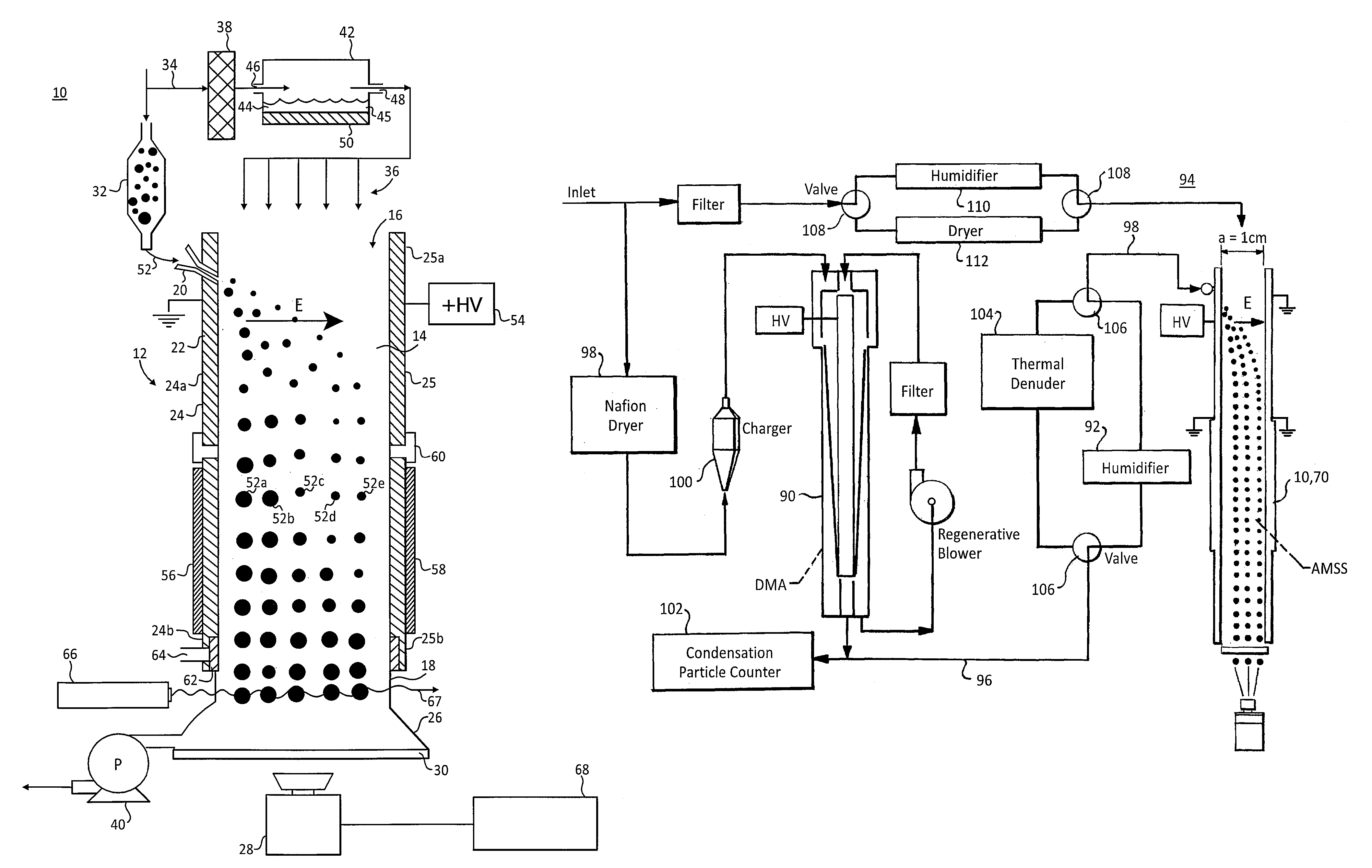
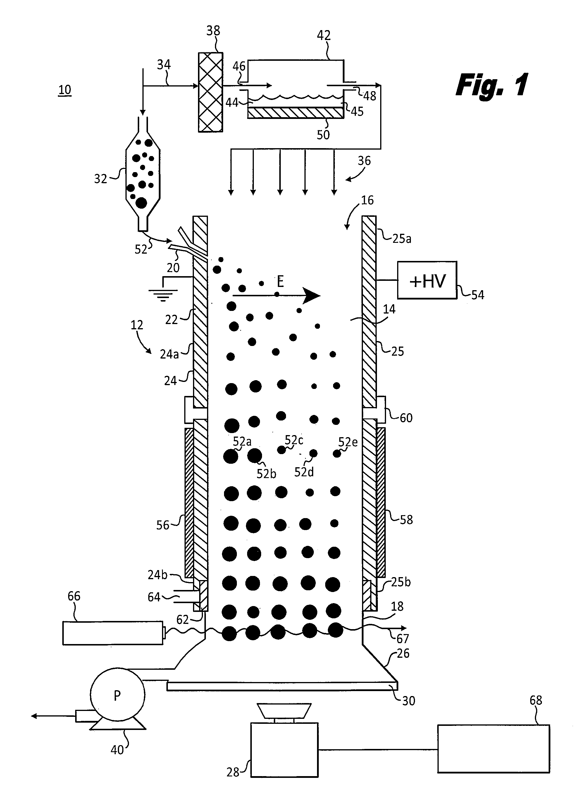
[0026]Referring first to FIG. 1, a schematic cross-section of a preferred form of an aerosol mobility size spectrometer 10, formed in accordance with the present invention, is shown. The spectrometer 10 generally includes a housing 12 and a camera 28 for detecting aerosol streams exiting the housing. The housing 12 defines an inner chamber 14 and includes an inlet 16, an outlet 18 and an aerosol injection port 20 adjacent the inlet. The inlet 16, the outlet 18 and the aerosol injection port 20 all communicate with the inner chamber 14. The housing 12 further includes a separation section 22, which applies an electric field E across the interior chamber 14, as will be described in further detail below.

[0027]The housing 12 may take various forms, but in the preferred embodiment, the housing includes two parallel walls 24 and 25 that are spaced apart a known distance. The spacing between the plates 24 and 25 is preferably about 1 cm and the widths of the plates are preferably about 10....


PUM

PropertyMeasurementUnit
time resolutionsaaaaaaaaaa
size distributionaaaaaaaaaa
particle sizesaaaaaaaaaa

Abstract

A device for measuring aerosol size distribution within a sample containing aerosol particles. The device generally includes a spectrometer housing defining an interior chamber and a camera for recording aerosol size streams exiting the chamber. The housing includes an inlet for introducing a flow medium into the chamber in a flow direction, an aerosol injection port adjacent the inlet for introducing a charged aerosol sample into the chamber, a separation section for applying an electric field to the aerosol sample across the flow direction and an outlet opposite the inlet. In the separation section, the aerosol sample becomes entrained in the flow medium and the aerosol particles within the aerosol sample are separated by size into a plurality of aerosol flow streams under the influence of the electric field. The camera is disposed adjacent the housing outlet for optically detecting a relative position of at least one aerosol flow stream exiting the outlet and for optically detecting the number of aerosol particles within the at least one aerosol flow stream.

Description

[0001]This invention was made with Government support under contract number DE-AC02-98CH10886, awarded by the U.S. Department of Energy. The Government has certain rights in the invention.BACKGROUND OF THE INVENTION[0002]The present invention relates generally to devices and methods for measuring ambient aerosol distributions and properties, and more particularly, to a device and method capable of accurately measuring submicron aerosol size distributions with high time resolution and signal to noise ratio.[0003]Aerosols refer to particles including solids, liquids and mixtures thereof suspended in a gas. Recent research has clearly demonstrated the significance of atmospheric aerosols on climate and air quality over regional and global scales. Atmospheric aerosols affect the climate by scattering and absorbing sunlight (direct effect) and by changing the microphysical structure, lifetime, and amount of clouds (indirect effect). The Intergovernmental Panel on Climate Change (IPCC) es...

Claims


Application Information

Patent Timeline
Patent Type & Authority Patents(United States)
IPC IPC(8): G01N21/00
CPCG01N15/0266G01N21/05
Inventor WANG, JIANKULKARNI, PRAMOD
Owner BROOKHAVEN SCI ASSOCS
Why Eureka
Try Eureka