
DPF regeneration monitoring method

a technology for dpf and regeneration monitoring, which is applied in the direction of machines/engines, electrical control, mechanical equipment, etc., can solve the problems of not being able to avoid potential damage to the dpf, not being able to respond to the dpf sufficiently fast, and having a 5 second delay

Active Publication Date: 2007-11-27
INT ENGINE INTPROP CO LLC
View PDF6 Cites 94 Cited by
  • Summary
  • Abstract
  • Description
  • Claims
  • Application Information

AI Technical Summary

Benefits of technology

The patent describes methods for regenerating a diesel particulate filter (DPF) in an exhaust system of a diesel engine. The methods involve monitoring the rate of combustion in the DPF and stopping the regeneration if the rate is too high. The methods also involve monitoring the amount of oxygen consumed in the DPF and stopping the regeneration if the temperature of the filter exceeds a certain threshold. These methods help to improve the efficiency and lifespan of the DPF in reducing emissions from diesel engines.

Problems solved by technology

A possibility exists for damage to the DPF if combustion of the deposits on the filter of the DPF becomes uncontrollable and the internal temperature of the DPF goes above a threshold.
A typical temperature sensor, such as those used to infer the rate of combustion in a DPF during a regeneration, has a response time that may not be sufficiently fast to avoid potential damage of the DPF under some conditions.
A 5 second delay may be detrimental to the ability of the ECU to terminate the regeneration when required.
Another disadvantage of using temperature sensors to infer the rate of combustion in the DPF is heat absorption by the bulk mass of the DPF.
Heat is absorbed by the bulk mass of the filter and surrounding casing of the DPF, thus further delaying the detected temperature increase in the exhaust gas downstream of the DPF.

Method used


Image

  • DPF regeneration monitoring method
  • DPF regeneration monitoring method
  • DPF regeneration monitoring method

Examples


Embodiment Construction

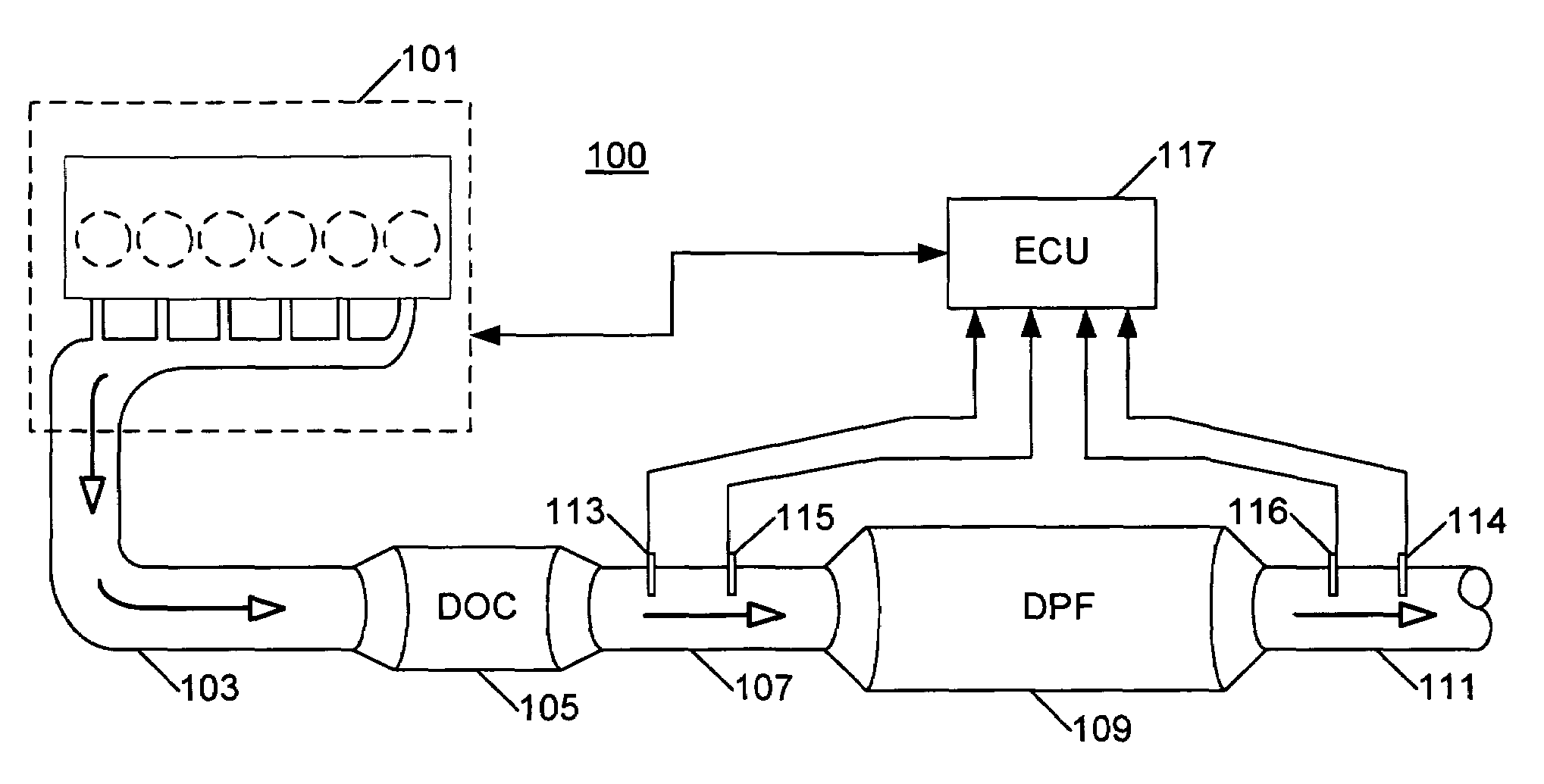
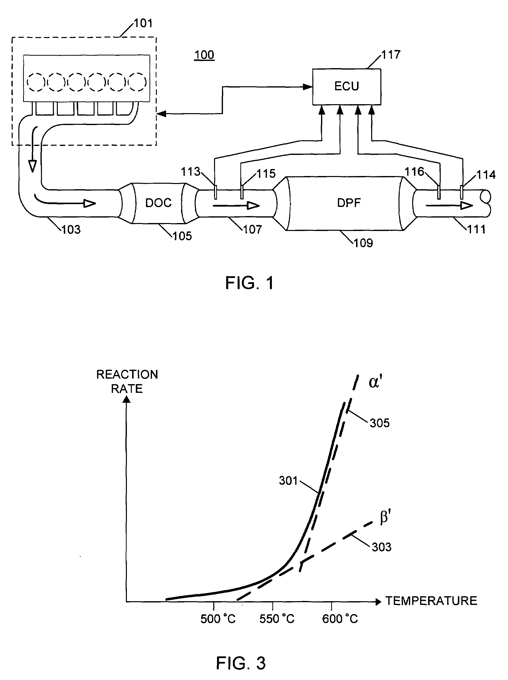
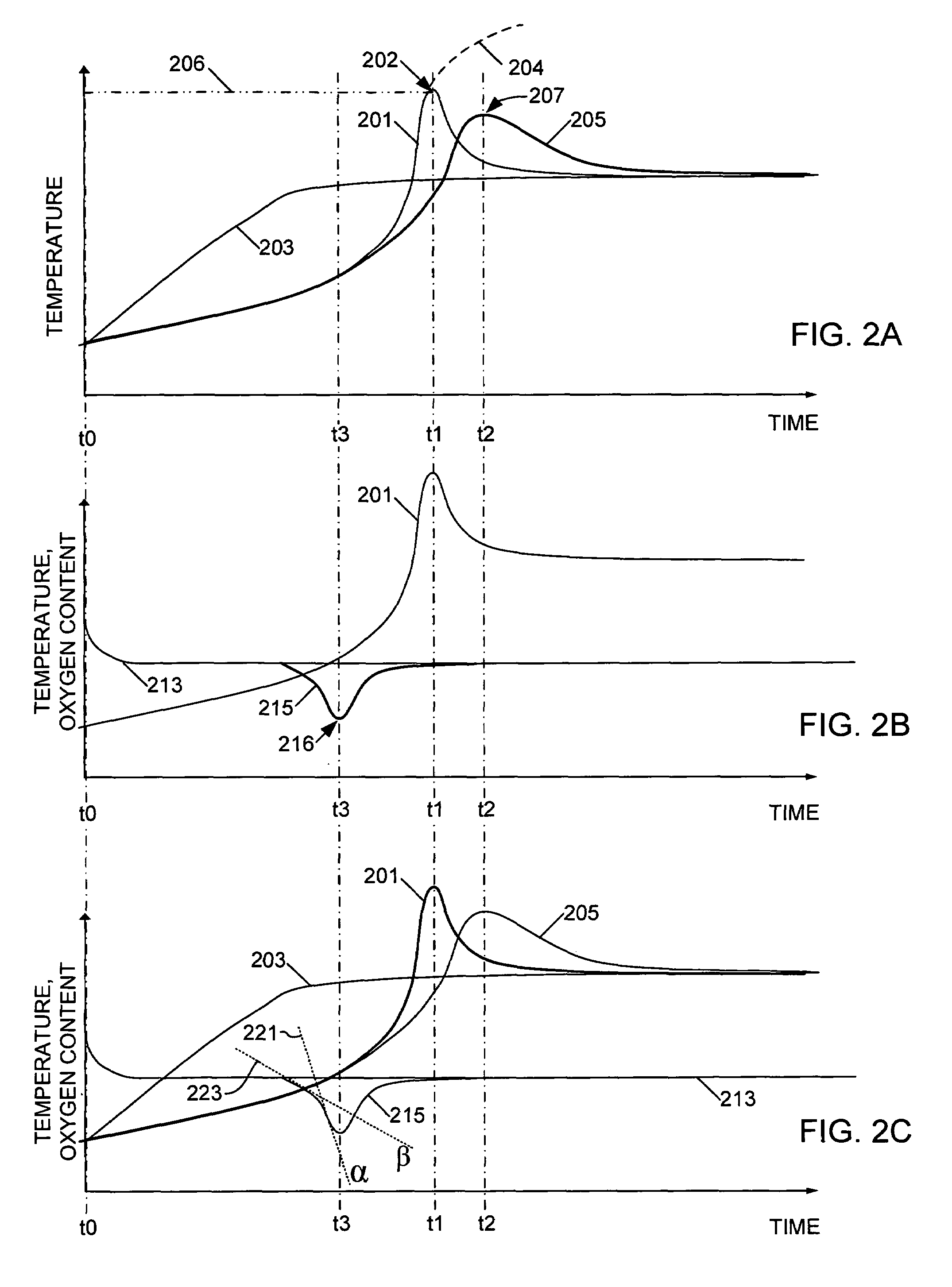
[0015]The following describes a method for sensing a condition that requires the premature termination of a regeneration event in a DPF including the use of oxygen sensors. A regeneration event of a DPF is an event during which solid material deposits trapped in the DPF combust to clean the DPF. Solid material trapped in the DPF includes primarily carbon, a byproduct of fuel combustion in the engine, and other materials. Oxygen sensors may be used in the intake and / or exhaust systems of an internal combustion engine to infer the rate of combustion of carbon matter accumulated on a filter element of a DPF. Based on the inferred rate of combustion, an engine ECU may be able to quickly halt the regeneration of the DPF and thus maintain a safe internal temperature in the DPF to avoid potential damage to the filter element.

[0016]An engine system 100 includes a base engine 101. The engine system 100 may include a compression ignition internal combustion or diesel engine. The base engine 1...


PUM


Abstract

A method for operating an internal combustion engine (100) and exhaust system therefor includes the step of initiating a regeneration event in a diesel particulate filter (DPF 109) (401). A first oxygen concentration (213) of a gas upstream of the DPF 109, and a second oxygen concentration (215) of the gas downstream of the DPF 109 are sensed (403) to infer a rate of combustion of material in the DPF (405) based on the difference between the first (213) and the second (215) oxygen concentrations. The rate of combustion is compared to a threshold value (409) and the regeneration event in the DPF 109 is terminated (411) if the rate of combustion is above the threshold.

Description

FIELD OF THE INVENTION [0001]This invention relates to exhaust gas treatment for internal combustion engines, including but not limited to, diesel particulate filter regeneration for compression ignition engines.BACKGROUND OF THE INVENTION [0002]Newer diesel engines have diesel particulate filters (DPF) incorporated in their exhaust systems to filter carbon and other particulates from the exhaust gas stream. When enough particulate material has accumulated on the filter element, the DPF begins to become plugged and needs to be regenerated. Regeneration is a process whereby deposits on the filter element of the DPF are induced to combust, typically by raising the engine exhaust temperature if necessary by appropriate engine operations. The combustion event of a DPF regeneration harmlessly cleans the filter element of the DPF of deposits. The regeneration process repeats as often as necessary to maintain smooth and reliable engine operation.[0003]In many diesel engines, an electronic ...

Claims


Application Information

Patent Timeline
Patent Type & Authority Patents(United States)
IPC IPC(8): F01N3/10
CPCF01N3/035F01N13/009F01N9/005F01N11/002F01N11/005F02D41/029F02D41/1441F02D41/1456F01N9/002F01N2560/025F01N2560/06F01N2560/14F02D41/144F02D41/1446F02D2200/0804F02D2200/0812Y02T10/47Y02T10/40
Inventor BARASA, PATRICK D.GUNDRUM, TIMOTHY J.
Owner INT ENGINE INTPROP CO LLC
Learn More