Systems and methods for vaporization of liquefied natural gas

a technology of liquefied natural gas and system, which is applied in the direction of container discharging method, container filling under pressure, lighting and heating apparatus, etc., can solve the problems of not meeting pipeline or other commercial specifications, the method mentioned above generally requires significant additional capital costs or has associated operational problems, and the option b>1/b> advanced by rogers is not very practical

Active Publication Date: 2007-11-27
BP CORP NORTH AMERICA INC
View PDF14 Cites 14 Cited by
  • Summary
  • Abstract
  • Description
  • Claims
  • Application Information

AI Technical Summary

Problems solved by technology

It is known that LNG produced from such remote locations in many instances when vaporized does not meet pipeline or other commercial specifications.
The methods mentioned above generally require significant additional capital costs or have operational problems associated with them.
For example, option 1 advanced by Rogers is not very practical as it would either require maintaining a separate inventory of LNG liquids with suitable GHV values, or very careful management of shipments of specific LNG liquids with suitable GHV values for blending with the remaining LNG contained within existing storage tanks.
Option 3 would require expensive equipment to conduct the injection into the vaporized LNG, including compressors for raising the pressure up to pipeline pressure, typically as high as 100 bar.
Option 4 advanced by Rogers, and the method disclosed in U.S. Pat. No. 6,564,579, would require expensive equipment to remove the desired amount of NGLs.
However, compressing the vapor to these high pressures requires considerable energy and expensive compressors and related equipment.

Method used


Image

  • Systems and methods for vaporization of liquefied natural gas
  • Systems and methods for vaporization of liquefied natural gas
  • Systems and methods for vaporization of liquefied natural gas

Examples


Embodiment Construction

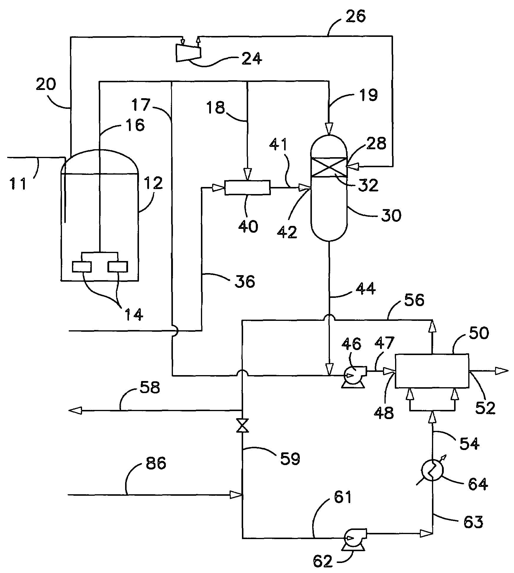
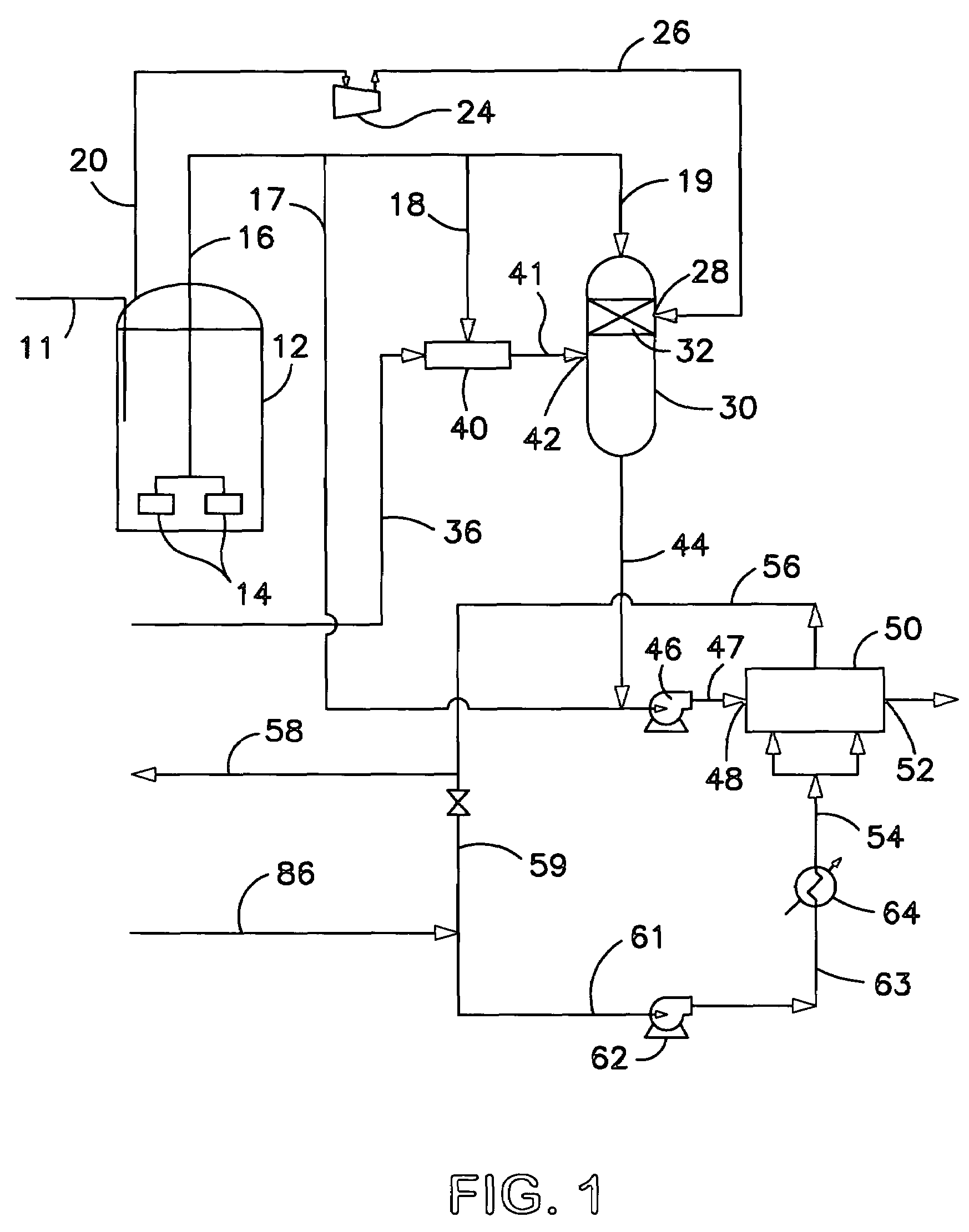
[0068]In the description of the Figures, the same numbers will be used to refer to the same or similar components. Further, not all heat exchangers, pumps, valves, and the like, necessary to achieve the accomplishment of the process, as known to those skilled in the art, have been shown for simplicity.

[0069]Referring now to FIG. 1, an embodiment of a system for vaporizing LNG in accordance with the present invention is shown. Typically, processes for vaporizing LNG are based upon a system wherein LNG is delivered, for instance, by an ocean going tanker via line 11 into LNG storage tank 12. Tank 12 is a cryogenic tank as known to those skilled in the art for storage of LNG. The LNG could alternatively be supplied by a process located adjacent to tank 12, by pipeline, or any other source.

[0070]As mentioned above, such LNG generally has a GHV which is higher than domestically produced natural gas present in pipelines or otherwise used commercially; typically the LNG imported from most ...


PUM

PropertyMeasurementUnit
temperatureaaaaaaaaaa
pressureaaaaaaaaaa
pressureaaaaaaaaaa

Abstract

Disclosed are methods and systems for vaporization of liquefied natural gas (LNG) that employ a condensing gas stream to adjust the gross heating value (GHV) of the LNG such that, upon vaporization, a natural gas product is obtained that meets pipeline or other commercial specifications. The condensing gas can be air, nitrogen, or in embodiments, NGLs such as ethane, propane, or butane, or other combustible hydrocarbon such as dimethyl ether (DME) depending on a desired change in GHV. In some embodiments, the methods and systems employ an integrated air separation plant for generation of nitrogen used as a condensing gas, wherein a cool stream of a heat transfer medium, such as water, ethylene glycol, other common heat transfer fluids, or mixtures thereof, obtained by heat transfer during vaporization of the LNG is used to pre-cool an air feed to the air separation plant, or to cool other process streams associated therewith.

Description

CROSS REFERENCE TO RELATED APPLICATIONS[0001]This application claims benefit of U.S. Provisional Application Ser. No. 60 / 529,693, filed Dec. 15, 2003, the teachings of which are incorporated herein by reference in their entirety.FIELD OF THE INVENTION[0002]The present invention relates generally to the storage and distribution of liquefied natural gas (LNG) and vaporization of the LNG into a natural gas product. More particularly, the present invention relates to systems and methods to modify the gross heating value (GHV) of the LNG so as to produce, upon vaporization, a natural gas product that meets pipeline or commercial specifications, or is otherwise interchangeable with domestically produced natural gas.BACKGROUND OF THE INVENTION[0003]Presently, the use of imported LNG is becoming increasingly important for many countries as the demand for natural gas continues to increase, while domestic production, particularly in the United States and Canada, has been on decline. The impor...

Claims


Application Information

Patent Timeline
Patent Type & Authority Patents(United States)
IPC IPC(8): F17C5/02B01J8/00C01B3/24C01B3/32F25J1/00F17C9/02F25J3/04
CPCF17C9/02F25J3/0403F25J3/04193F25J3/04272F25J3/04296F25J3/04381F25J3/044F25J3/04563F25J3/04969F17C2265/037F25J2210/62F25J2230/04F25J2270/904F17C2221/033F17C2223/0161F17C2223/033F17C2225/0123F17C2225/036F17C2227/0135F17C2227/0309F17C2227/0393F17C2265/05
Inventor WARD, PATRICK B.
Owner BP CORP NORTH AMERICA INC
Why Eureka
Try Eureka