Microstructured optical fibers and methods

a microstructured optical fiber and microstructure technology, applied in the field of optical fibers, to achieve the effects of improving the bend performance of optical fibers, reducing refractive index, and increasing attenuation

Inactive Publication Date: 2008-11-11
CORNING INC
View PDF21 Cites 186 Cited by
  • Summary
  • Abstract
  • Description
  • Claims
  • Application Information

AI Technical Summary

Benefits of technology

[0008]One aspect of the present invention relates to a method of making an optical fiber comprising forming via chemical vapor deposition (CVD) operation a soot containing optical fiber preform. The soot preform is consolidated in a gaseous atmosphere which surrounds the preform under conditions which are effective to trap a portion of the gaseous atmosphere in the preform during said consolidation step, thereby resulting in the formation of non-periodically distributed holes or voids in the consolidated preform, each hole corresponding to a region of at least one trapped consolidated gas within the consolidated glass preform. The consolidated preform having holes therein is then used to make an optical fiber. At least some of the holes formed in the optical fiber preform during the consolidation step remain in the drawn optical fiber. By designing the hole containing region to correspond to the cladding of the optical fiber, these resultant optical fiber can be made to exhibit a core region with a first refractive index and a cladding region having a second refractive index lower than that of the core, the lower refractive index at least partly due to the presence of the holes in the cladding. Alternatively or additional the methods disclosed herein can be used to provide a hole containing region within the cladding to thereby improve the bend performance of the optical fibers. For example, using the fiber designs and methods disclosed herein, it is possible to create optical fiber which exhibits an increase in attenuation at 1550 nm when bent around a 10 mm mandrel which is less than 20 dB / turn, more preferably less than 15 dB / turn, and even more preferably less than 10 dB / turn. Similarly, using the fiber designs and methods disclosed herein, it is possible to create an optical fiber which exhibits an attenuation increases at 1550 nm of less than 3 dB / turn, more preferably less than 1 dB / turn, even more preferably less than 0.5 dB / turn, and most preferably less than 0.25 dB / turn when bent around a 20 mm diameter mandrel. The methods and fiber designs described herein are useful for making both fibers that are single moded and fibers that are multimoded at 1550 nm.
[0015]The fibers disclosed herein can be made using a relatively low cost manufacturing process, because expensive dopants such as fluorine and / or germania can be avoided, if desired, and the stack and draw manufacturing process can likewise be avoided. The invention will also enable flexible dispersion control (positive, flat or negative), for example, the achievement of large positive dispersion (>30 ps / nm / Km at 1550 nm) for signal processing, or negative dispersion fibers (e.g., <−200 ps / nm / Km at 1550 nm) which could be useful for dispersion compensation. Alternatively, the methods disclosed herein can be used simply to add voids to a cladding of a fiber which is doped with one or more of germania, phosphorous, aluminum, ytterbium, erbium, fluorine or other conventional fiber dopant materials, to increase the bend resistance thereof. In another alternative embodiment, the methods disclosed herein can be used to make a silica core (i.e., a fiber having no germanium dopant in the core) fiber which has a cutoff wavelength below 800 nm and a numerical aperture greater than about 0.08, more preferably greater than about 0.10 at 1550.

Problems solved by technology

However, use of germania and / or fluorine is not critical and, for example, the fiber could if desired be entirely or substantially devoid of both germania and fluorine.

Method used


Image

  • Microstructured optical fibers and methods
  • Microstructured optical fibers and methods
  • Microstructured optical fibers and methods

Examples


example 1

[0051]3000 grams of SiO2 (0.48 g / cc density) soot were deposited using an outside vapor deposition process to form an SiO2 soot blank, i.e., by depositing onto a 1 meter long×10 mm diameter removable alumina bait rod. The alumina bait rod was removed and an 8 mm diameter core cane consisting of pure (undoped) consolidated silica was inserted into the SiO2 soot blank. This rod in soot assembly was then sintered as follows. The assembly was first dried for 2 hours in an atmosphere of 97 percent helium and 3 percent chlorine at 1000° C. followed by down driving at 32 mm / min (resulting in an increase in temperatures of the preform of approximately 16° C. / min.) through a hot zone set at 1500° C. in a 100 percent nitrogen sintering atmosphere. The preform assembly was than re-down driven (i.e., a second time) through the hot zone at 25 mm / min (approximately 12.5° C. / min. heat up rate of the preform), then final sintered at 6 mm / min (approximately 3° C. / min heat up rate) in order to sinter...

example 2

[0053]3000 grams of SiO2 (0.47 g / cc density) soot were flame deposited onto a 1 meter long×8 mm diameter pure silica core cane. This assembly was then sintered as follows. The assembly was first dried for 2 hours in an atmosphere consisting of helium and 3 percent chlorine at 1000° C. followed by down driving at 32 mm / min through a hot zone set at 1500° C. in a 70 percent nitrogen and 30 percent helium (by volume) atmosphere, then re-down driven through the hot zone at 25 mm / min, then final sintered at 6 mm / min, in order to sinter the soot to a nitrogen / helium-seeded overclad blank. The blank was placed for 24 hours in an argon purged holding oven set at 1000° C. to outgas the helium from the blank.

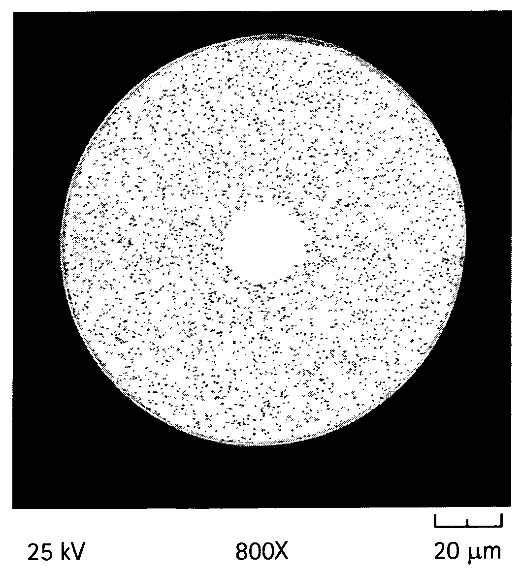
[0054]The blank was drawn to 125 micron diameter fiber in a manner similar to Example 1. SEM analysis of the end face of a fiber showed about 22 micron diameter solid silica core and a cladding containing 4.5 regional void area percent nitrogen filled voids with an average diameter of 0.4...

example 3

[0055]3000 grams of SiO2 (0.46 g / cc density) soot were flame deposited onto a 1 meter long×8 mm diameter pure silica core cane from Step 1. This assembly was then sintered as follows. The assembly was first dried for 2 hours in an atmosphere consisting of 3 percent chlorine gas, the remainder helium, at 1000° C. followed by down driving at 32 mm / min through a hot zone set at 1500° C. in a 50 percent nitrogen / 50 percent helium (by volume) atmosphere. The assembly was then re-down driven through the same hot zone at 25 mm / min, after which the assembly was re-down driven through the same hot zone for final sintering at 6 mm / min) in order to sinter the soot to a nitrogen / helium-seeded overclad blank. The blank was placed for 24 hours in an argon purged holding oven set at 1000° C. to outgas the helium from the preform blank.

[0056]The resultant optical fiber preform was drawn to 125 micron diameter fiber in a manner similar to Example 1. SEM analysis of the end face of a fiber showed a 2...


PUM

PropertyMeasurementUnit
diameteraaaaaaaaaa
diameteraaaaaaaaaa
diameteraaaaaaaaaa

Abstract

Microstructured optical fiber and method of making. Glass soot is deposited and then consolidated under conditions which are effective to trap a portion of the consolidation gases in the glass to thereby produce a non-periodic array of voids which may then be used to form a void containing cladding region in an optical fiber. Preferred void producing consolidation gases include nitrogen, argon, CO2, oxygen, chlorine, CF4, CO, SO2 and mixtures thereof.

Description

CROSS-REFERENCE TO RELATED APPLICATIONS[0001]This application claims the benefit of priority under 35 U.S.C. § 119(e) of U.S. Provisional Application Ser. No. 60 / 734,995 filed on Nov. 8, 2005, Provisional Application Ser. No. 60 / 789,798 filed on Apr. 5, 2006, and Provisional Application Ser. No. 60 / 845,927 filed on Sep. 20, 2006, the contents of which are relied upon and incorporated herein by reference in their entirety.BACKGROUND OF THE INVENTION[0002]1. Field of the Invention[0003]The present invention relates generally to optical fibers, and more specifically to microstructured optical fibers and methods for making microstructured optical fibers.[0004]2. Technical Background[0005]Optical fibers formed of glass materials have been in commercial use for more than two decades. Although such optical fibers have represented a quantum leap forward in the field of telecommunications, work on alternative optical fiber designs continues. One promising type of alternative optical fiber is...

Claims


Application Information

Patent Timeline
Patent Type & Authority Patents(United States)
IPC IPC(8): G02B6/02
CPCC03B37/01446C03B37/02781G02B6/02357C03C13/00C03C13/04G02B1/048C03B2201/02C03B2201/31C03B2203/14G02B6/02333C03B2203/42C03B37/014C03B37/027G02B6/032
Inventor BOOKBINDER, DANA CRAIGFIACCO, RICHARD MICHAELLI, MING-JUNMURTAGH, MICHAEL THOMASTANDON, PUSHKAR
Owner CORNING INC
Why Eureka
Try Eureka