Device for laying line elements

a technology of laying device and laying line, which is applied in the direction of cable arrangement between relatively moving parts, machine supports, manufacturing tools, etc., can solve the problems of large cable load, shorten the life of the cable w, and increase the diameter of the cable, so as to achieve the effect of convenient application

Active Publication Date: 2007-11-27
FANUC LTD
View PDF17 Cites 25 Cited by
  • Summary
  • Abstract
  • Description
  • Claims
  • Application Information

AI Technical Summary

Benefits of technology

[0013]Therefore, an object of the present invention is to provide a device for laying line elements, which can be easily applied to a portion having an outer member and an inner member rotatable in relation to each other, such as an articulating portion of a robot, especi...

Problems solved by technology

However, the above prior arts involve the following problems (1)-(3).
In the case of a small gap between the outer member A and the inner member B, if this configuration is applied to the cable W, the U-shaped turned portion thereof will have a large curvature, which can bring about a large load on the cable W thereby to cause a problem of shortening the life of the cable W.
(3) In the case of using the technique in which the cable W is laid so as to extend in a...

Method used


Image

  • Device for laying line elements
  • Device for laying line elements
  • Device for laying line elements

Examples


Embodiment Construction

[0032]With reference to the drawings, several embodiments of the present invention will be described below.

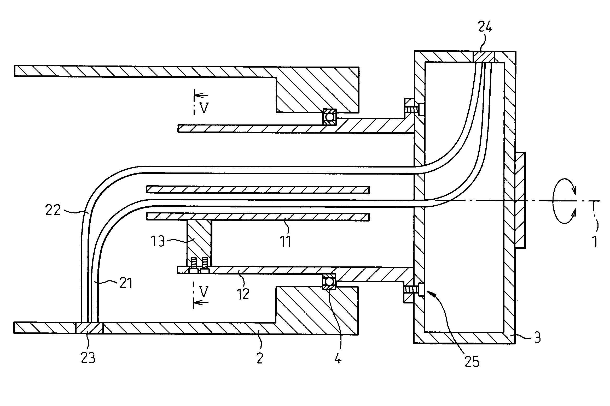
[0033]Firstly, FIGS. 4 and 5 are referred to. A structure shown in FIG. 4, which is used, for example, in a wrist portion of a robot, includes a hollow disk-like member (first member) constituting a moving housing 3, and a hollow cylindrical member (second member) constituting a stationary housing 2.

[0034]A pipe member 12 having a center axis 1 is attached to the moving housing 3 by fasteners 25 such as bolts and is rotatably supported in the cylindrical stationary housing 2 by means of bearings 4. Thus, the pipe member 12 and the moving housing 3 are supported by the stationary housing 2 so as to be rotatable about the center axis 1.

[0035]As shown in FIG. 5, another pipe member 11 is disposed inside the pipe member 12 in a generally coaxial relationship with the pipe member 12, and these pipe members 11 and 12 are coupled at parts thereof to each other by means of a coupling m...


PUM


Abstract

A device used to lay line elements such as electric and/or fluid lines between a stationary housing and a moving housing. The device includes a double pipe structure having an inner pipe member and an outer pipe member. The outer pipe member is attached to the moving housing and rotatably supported by the stationary housing. The inner and outer pipe members are arranged in a generally coaxial relationship and coupled to each other by a coupling member. The line elements, which extend between a holding portion on the stationary housing and a holding portion on the moving housing, are divided into first and second groups, and the first group of line elements is laid to extend through an inner hole of the inner pipe member while the second group of line elements is laid to extend through an annular gap formed between the inner and outer pipe members.

Description

BACKGROUND OF THE INVENTION[0001]1. Field of the Invention[0002]The present invention relates to a laying device for laying line elements in a machine having a first member and a second member rotatable relative to each other about a rotation axis thereof, which is applied to the circumference of those members. The laying device according to the present invention is typically used for electric and / or fluid supply lines in a wrist portion of an industrial robot.[0003]2. Description of the Related Art[0004]For example, a wrist portion of an industrial robot (referred to simply as a “robot” hereinafter) includes a structure provided with a first member and a second member rotatable in relation to each other about a rotation axis. Several prior arts are known for laying one or more electric / fluid lines in the circumference of such members rotatable in relation to each other. Typical examples are shown in FIGS. 1-3.[0005]In a first prior art shown in FIGS. 1A and 1B, an outer member A an...

Claims


Application Information

Patent Timeline
IPC IPC(8): B25J19/00H01R35/02H02G11/00
CPCB25J19/0029H02G11/00Y10T74/20311H01R35/02
Inventor UEMATSU, MASAAKIMATSUMOTO, KUNIYASUNAKAGAWA, HIROSHIMORIOKA, MASAHIRO
Owner FANUC LTD
Why Eureka
Try Eureka