Method and apparatus for an action system for a firearm

a technology of action system and firearm, applied in the field of firearms, can solve problems such as disproportionate bulky mechanisms, and achieve the effect of low maintenance and reliabl

Active Publication Date: 2007-11-27
SNAKE RIVER MACHINE
View PDF22 Cites 44 Cited by
  • Summary
  • Abstract
  • Description
  • Claims
  • Application Information

AI Technical Summary

Benefits of technology

[0006]The present invention is a roller-lock delayed blowback mechanism providing a compact, low-maintenance, reliable, and lightweight action system for a firearm, preferably a semi-automatic shotgun. A primary roller-lock mechanism is located to the rear of the feeding and ejecting ports of the firearm and preferably contained within the approximate diameter of a cartridge.
[0007]An alternative embodiment of the present invention further incorporates a secondary, or compounding, roller-lock mechanism within the action system to further delay the opening of the firearm chamber. This is advantageous because locating the locking rollers to the rear of the ejection port obviates the use of a relatively long and proportionately heavy bolt in which the rollers are caged. Thus, a relatively lighter bolt carrier—to be accelerated past inwardly pinching rollers—provides less inertial resistance to the accelerating force than prior conventional designs wherein the bolt carrier is proportionately larger, heavier, and more resistant to acceleration. That is, the reduced delaying effect of the primary roller-lock mechanism brought about by the necessarily diminished physical space requirements, has been increased by compounding the primary roller-lock mechanism rather than by adding mass. In the preferred embodiment, the inertia of a relatively lesser mass (the firing pin and striking hammer) sufficiently delays the opening of the firing chamber until the explosive pressure within is reduced to a safe level by retarding the movement of the bolt carrier relative to the bolt, which in turn retards the movement of the bolt relative to the barrel and receiver of the shotgun. The compounding or additional stage of roller-lock delay is increased similar in effect to compounding a 1:10 gear ratio to produce a 1:100 ratio.

Problems solved by technology

This is likely because the large diameter of the cartridge would require a disproportionately bulky mechanism and would interfere with the space necessary for feeding and ejecting the cartridges when situated near the front of the bolt—as in all previous known designs.

Method used


Image

  • Method and apparatus for an action system for a firearm
  • Method and apparatus for an action system for a firearm
  • Method and apparatus for an action system for a firearm

Examples


Embodiment Construction

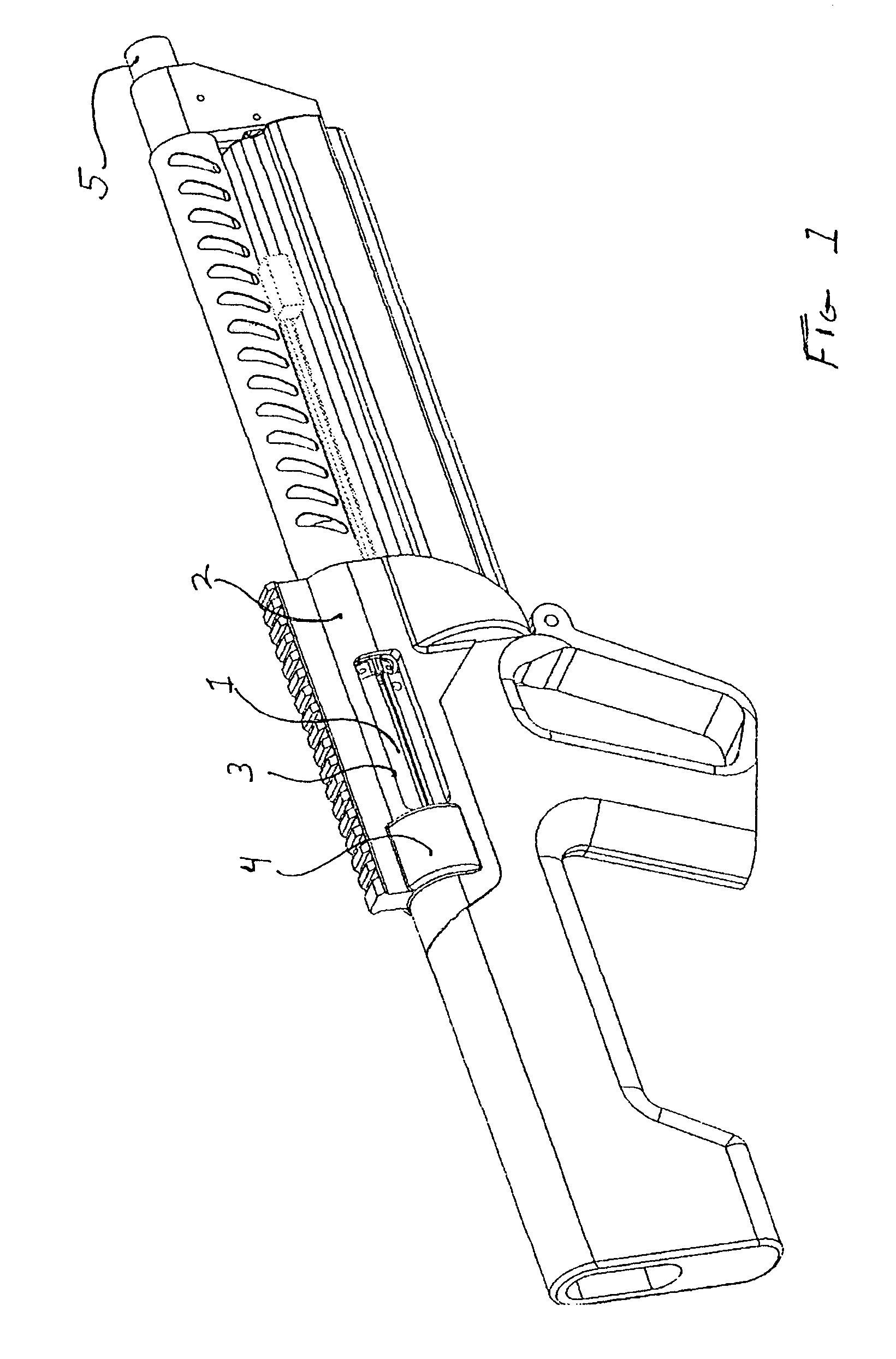
[0017]FIG. 1 depicts a semi-automatic shotgun having a roller-lock mechanism deployed within a reinforcing boss 4 on a receiver 2. A bolt 1 rides within the receiver 2 to close a firing chamber 20 in a barrel 5. The bolt 1 extends rearward past an ejection port 3 when out of battery position. It should be noted that in this and other figures, certain details of the firearm not related to the patentable aspects of the present invention—such as the trigger mechanism and magazine-are not enumerated.

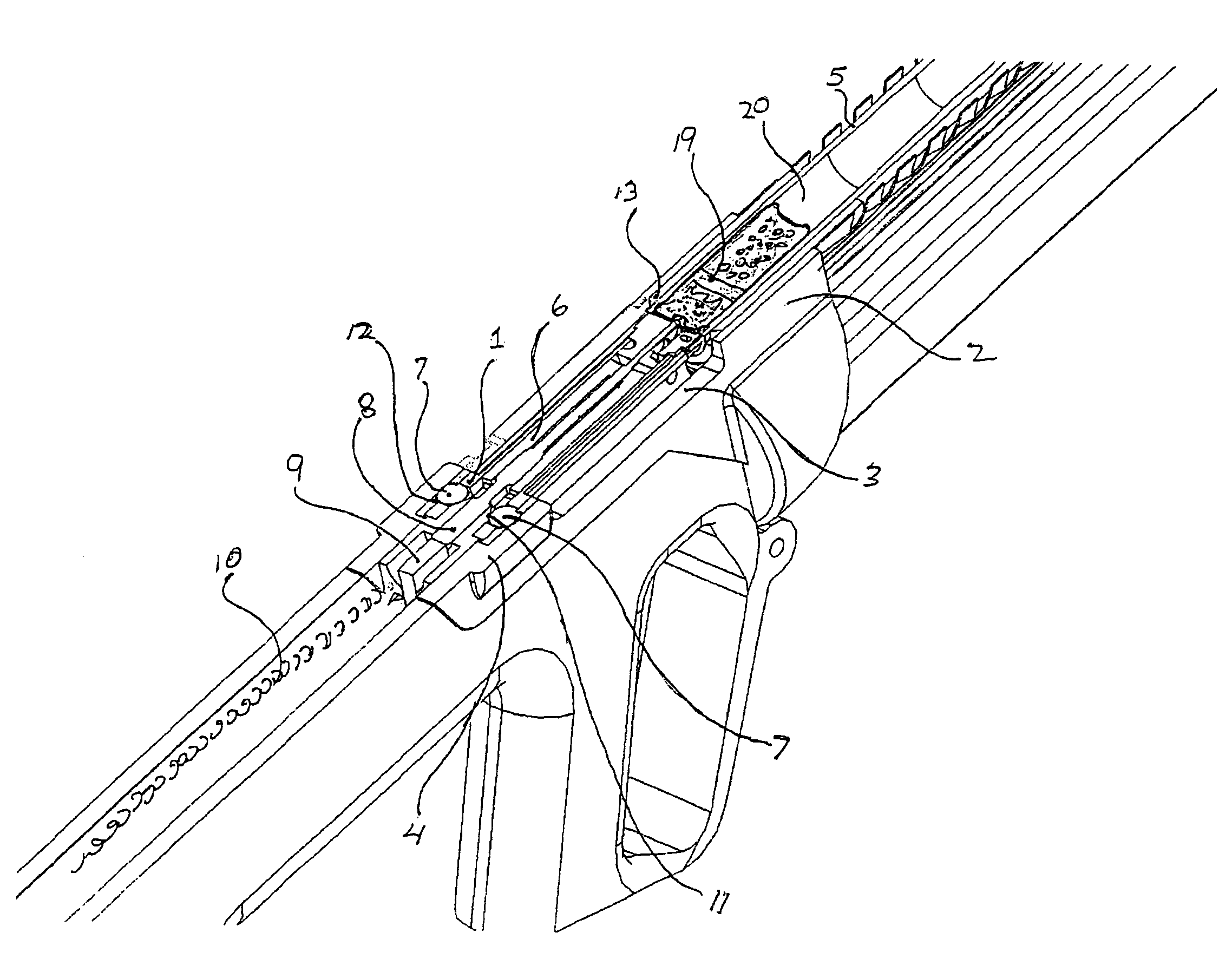
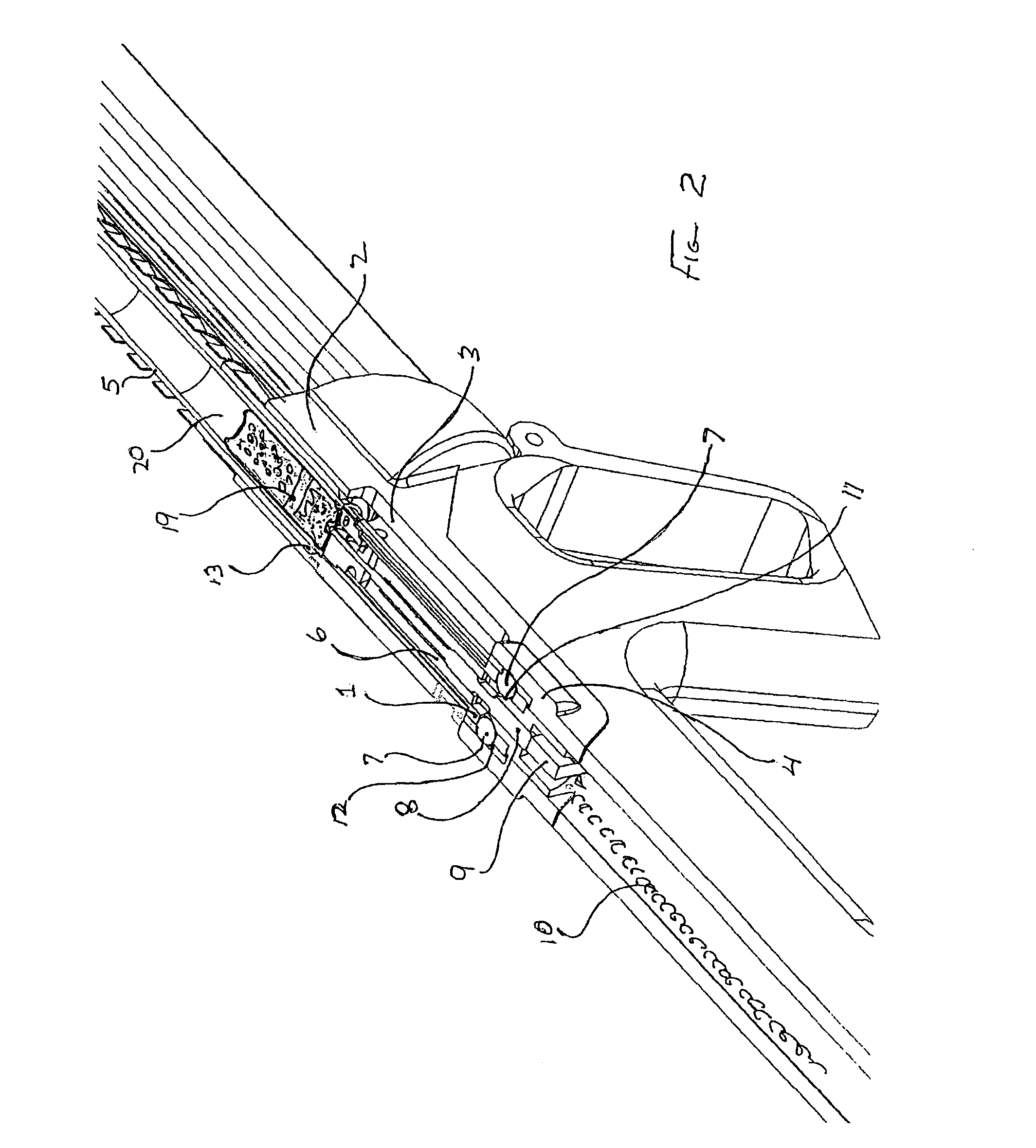
[0018]FIGS. 2 and 6 depict a partial horizontal cross-sectional view about the centerline of the firearm barrel 5 showing the primary roller-lock mechanism of one embodiment of the present invention. The primary roller-lock mechanism is positioned rearward of the ejection port 3 and preferably comprises the bolt 1, a bolt carrier 6, primary bearing(s) 7 (e.g., roller(s)), and a barrel extension 13. When the cartridge 19 is fired by a hammer 9 impinging on a firing pin 8, the explosive gas pr...


PUM


Abstract

A method and apparatus providing an action system for a firearm. The action system includes a primary roller-lock mechanism located rearward of an ejection port. The primary roller-lock mechanism includes a bolt and a first primary roller caged within the bolt. A bolt carrier ramp is attached to a bolt carrier. A barrel extension ramp is attached to a barrel extension. The first primary roller, bolt carrier ramp, and barrel extension ramp cooperate to effectively delay movement of the bolt and bolt carrier in response to firing of the firearm.

Description

[0001]This application claims the benefit of U.S. Provisional Patent App. No. 60 / 526,540, entitled “Action System For A Firearm,” filed Dec. 3, 2003; the contents of which are expressly incorporated herein by reference.BACKGROUND OF THE INENTION[0002]1. Technical Field[0003]The invention relates generally to the field of firearms, and more specifically to the operating system of a firearm.[0004]2. Background of the Invention[0005]The roller-lock delayed blowback action system has been employed in rifles and sub-machine guns since the 1950's and is well known to those familiar with firearm design, but it has not previously been employed in a semi-automatic shotgun. This is likely because the large diameter of the cartridge would require a disproportionately bulky mechanism and would interfere with the space necessary for feeding and ejecting the cartridges when situated near the front of the bolt—as in all previous known designs. However, it is desirable to provide a roller-lock dela...

Claims


Application Information

Patent Timeline
Patent Type & Authority Patents(United States)
IPC IPC(8): F41A3/36F41A1/00F41A3/46
CPCF41A3/46
Inventor HAJJAR, JEFFREYSTOCKTON, WARREN
Owner SNAKE RIVER MACHINE
Why Eureka
Try Eureka