Solar cell array

a solar array and solar cell technology, applied in the field of solar cell arrays, can solve the problems of reducing efficiency, reducing volume during launch, and the most expensive component of solar array, and achieve the tightest possible packing of solar panels, reduce volume, and reduce the effect of volum

a solar array and solar cell technology, applied in the field of solar cell arrays, can solve the problems of reducing efficiency, reducing volume during launch, and the most expensive component of solar array, and achieve the tightest possible packing of solar panels, reduce volume, and reduce the effect of volum

US7301095B2Inactive Publication Date: 2007-11-27NORTHROP GRUMMAN SYST CORP

Image

  • Solar cell array
  • Solar cell array
  • Solar cell array

Examples


Embodiment Construction

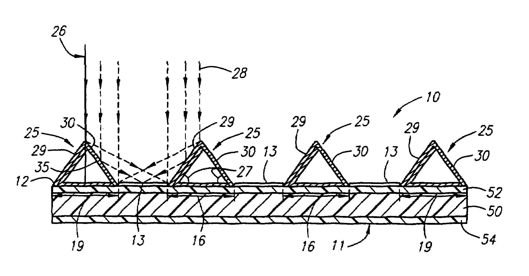
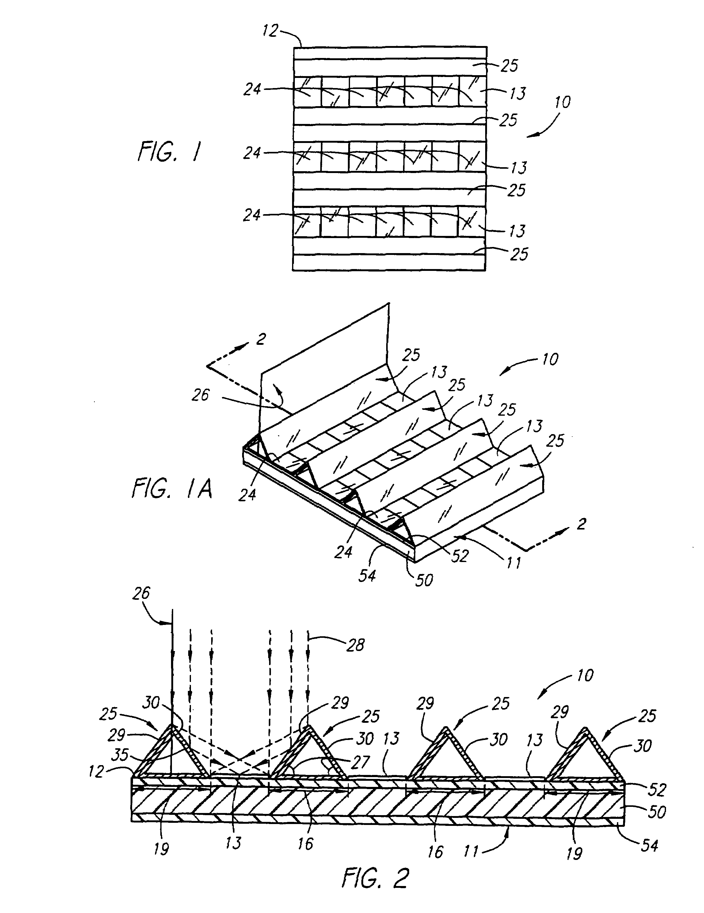
[0049]A preferred embodiment of a solar panel 10 according to the present invention is shown in FIGS. 1, 1A, and 2.

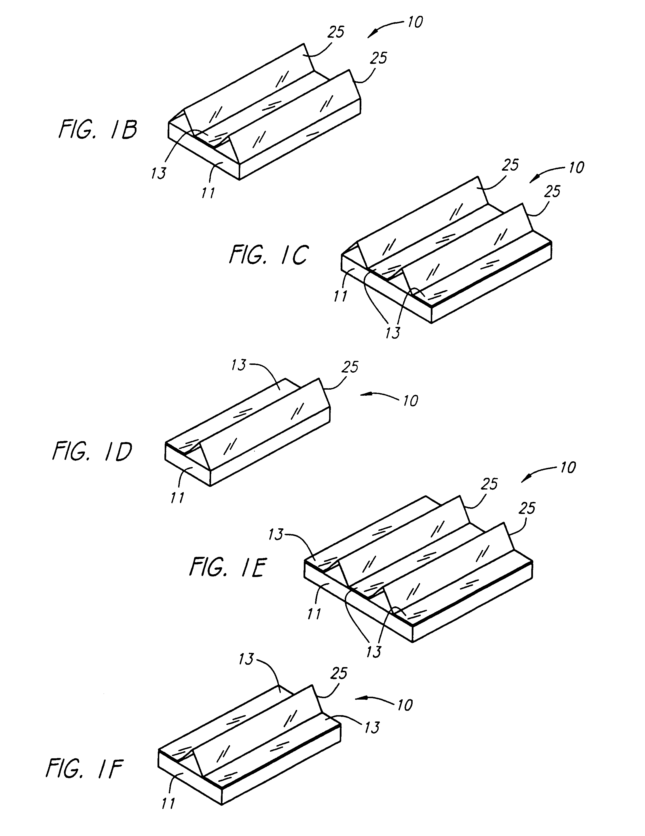
[0050]Solar panel 10 comprises a base 11 having a front surface 12, a plurality of generally parallel rows 13 of solar cells 24 mounted on the front surface 12 of the base 11, and a plurality of elongated collapsible, self-deploying reflectors 25 mounted on the front surface 12 of the base 11. As shown, rows 13 of solar cells 24 and reflectors 25 are preferably mounted on the front surface 12 of base 11 in an alternating fashion. Adjacent rows 13 are, therefore, preferably spaced apart by spacings 16. Edge spacings 19 are also preferably provided next to the two outside rows 13. Elongated reflectors 25, which comprise two reflective sides 29, 30, are then mounted in the spacings 16 provided between the rows 13 and in the edge spacings 19 provided at the edges of the base 11. In this manner, a reflector 25 is interposed between each of the adjacent rows 13 of solar cells...


PUM


Abstract

A solar panel for a spacecraft has a base with a face, and at least one row of solar cells and at least one elongated reflector are mounted on the face of the base. The reflectors and the rows are mounted generally parallel to each other in an alternating fashion. The reflector has first and second reflecting sides when the reflector is in a deployed position. The reflector is mounted so that the first side of the reflector is adjacent to a row of solar cells and reflects radiation incident on the first side onto the adjacent row of solar cells when the reflector is in a deployed position. Preferably, a plurality of rows and a plurality of reflectors are mounted on the face of the base, with at least one of the reflectors being disposed between two adjacent rows of solar cells.

Description

CROSS-REFERENCE TO RELATED APPLICATIONS[0001]This application is a continuation of application Ser. No. 10 / 351,454, filed Jan. 24, 2003 now abandoned, which is a continuation of application Ser. No. 09 / 559,815, filed Apr. 25, 2000 now abandoned, which is a continuation-in-part of application Ser. No. 09 / 337,624, filed Jun. 21, 1999, now U.S. Pat. No. 6,177,627, issued Jan. 23, 2001, which are hereby incorporated by reference as if they were set forth herein in their entirety.FIELD OF THE INVENTION[0002]The present invention relates to solar cell arrays for use on spacecraft and, in particular, solar cell arrays for powering spacecraft during long missions in space.BACKGROUND OF THE INVENTION[0003]Spacecraft generally use solar cells to collect solar radiation and convert it into the electrical power necessary to operate the spacecraft. The solar cells are normally disposed on a solar array. A solar array typically comprises one or more solar panels electrically attached to each othe...

Claims


Application Information

Patent Timeline
27 Nov 2007
Publication
US7301095B2
IPC
H01L25/00; F24S23/70; H01L31/042; H01L31/052
CPC
B64G1/443; F24J2/16; H01L31/0547; H02S30/20; H01L31/042; F24J2/52; F24J2002/108; F24J2002/5486
Inventors
MURPHY, DAVID M.; ESKENAZI, MICHAEL I.