Turn signal lamp, periphery monitoring device, body construction and imaging device for vehicle

a technology of turn signal lamp and imaging device, which is applied in the direction of television system, fire alarm, instruments, etc., can solve the problems of affecting the viewability of images and difficulty for the vehicle driver to s

Active Publication Date: 2007-11-27
TOYOTA JIDOSHA KK
View PDF31 Cites 87 Cited by
  • Summary
  • Abstract
  • Description
  • Claims
  • Application Information

AI Technical Summary

Benefits of technology

[0007]An object of the invention is to provide a vehicle side turn signal light, a vehicle periphery monitoring device, a vehicle body construction, and a vehicle imaging device which can realize a dazzle inhibiting effect for a shot image when a side turn signal light included in an imaged zone is lit.

Problems solved by technology

As a result, according to the above system, even at night, or the like, it is possible to ensure the visibility of the blind spot zone that it is difficult for the vehicle driver to see.
In this case, infrared light component which is generated by lighting of the side turn signal light and which is incident on the camera becomes excessive, and thus the side turn signal light in the image of the camera has a dazzling appearance, and the viewability of the image falls substantially.

Method used


Image

  • Turn signal lamp, periphery monitoring device, body construction and imaging device for vehicle
  • Turn signal lamp, periphery monitoring device, body construction and imaging device for vehicle
  • Turn signal lamp, periphery monitoring device, body construction and imaging device for vehicle

Examples


first embodiment

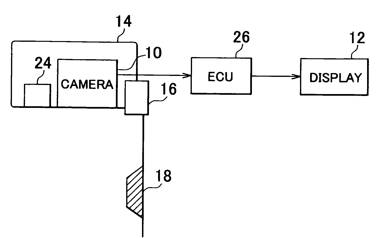
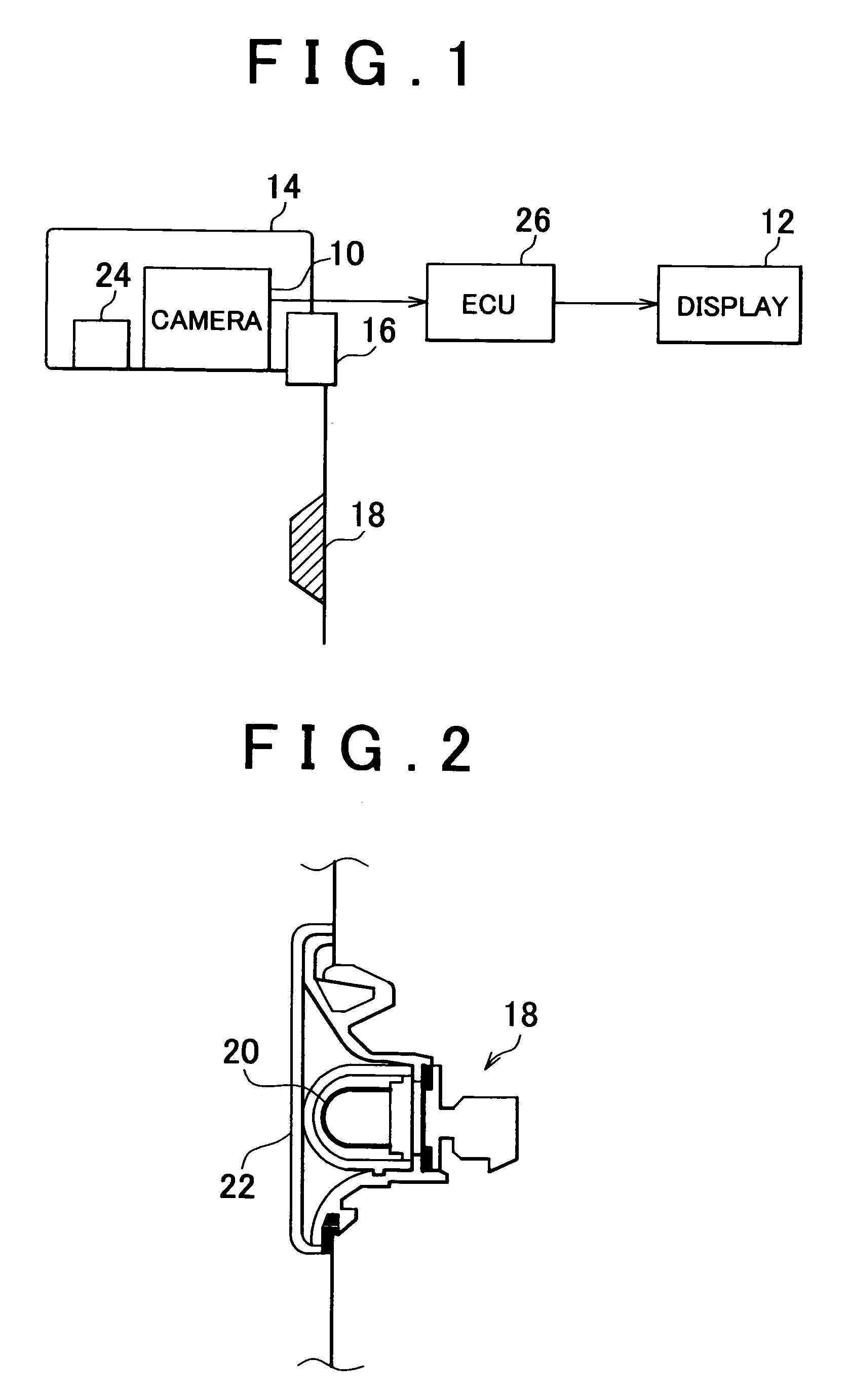
[0036]FIG. 1 shows a system configuration of a vehicle periphery monitoring device of the invention. The vehicle periphery monitoring device according to this embodiment is a device that uses a camera mounted on a vehicle to visibly display a vehicle periphery state to a user of the vehicle. According to this embodiment, the vehicle periphery monitoring device is provided with a camera 10 and a display 12.

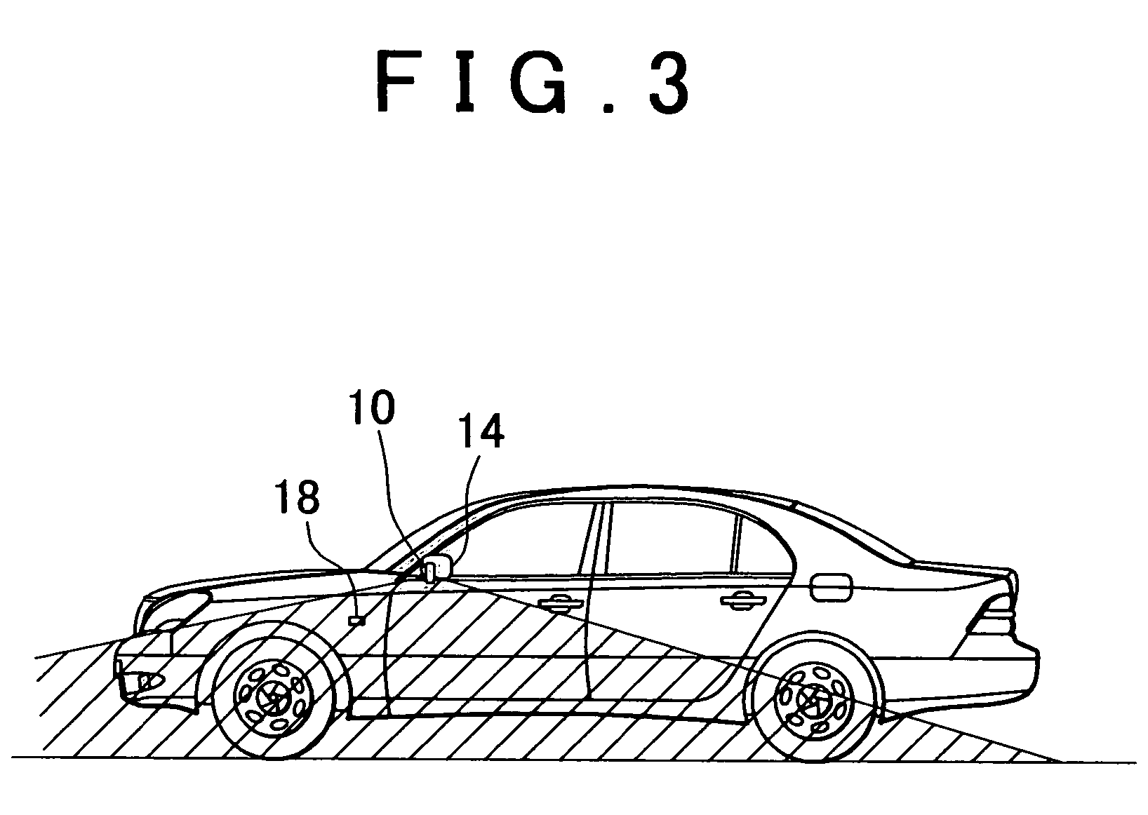
[0037]The camera 10 is provided on a door mirror 14 that is an outer mirror attached to a side door that can be open and shut. This side door is on the opposite side of the vehicle to the driver's seat (note that, the camera 10 may also be provided on the driver's seat side). A mirror storage mechanism 16 is provided in the door mirror 14 that allows an operation position of the door mirror 14 to be changed in accordance with operation of an occupant of the vehicle, or the like. The door mirror 14 is configured such that its operation position can be selectively switched between a ...

second embodiment

[0055]Next, the invention will be explained with reference to FIG. 5.

[0056]In the first embodiment described above, in order to achieve the dazzle inhibiting effect for the camera image, the near-infrared light reduction processing is executed for the side turn signal light 18. In contrast to this, in the second embodiment, the dazzle inhibiting effect for the camera image is achieved by shielding an optical path that linearly connects a side turn signal light 18 and the camera 10, instead of by executing the near-infrared light reduction processing of the side turn signal light 18.

[0057]FIG. 5 shows a perspective view of a side turn signal light 100 of this embodiment. Note that, in FIG. 5, structural elements that are the same as those shown in FIGS. 1 and 2 are denoted with the same reference numerals, and thus an explanation thereof is either omitted or simplified. With the system of this embodiment, the side turn signal light 100 is, like the side turn signal light 18, a light ...

third embodiment

[0063]Next, the invention will be described with reference to FIGS. 6 and 7.

[0064]FIG. 6 shows a system configuration of a vehicle periphery monitoring device of the third embodiment. In FIG. 6, structural elements that are the same as those shown in FIG. 1 are denoted with the same reference numerals, and thus an explanation thereof is either omitted or simplified. In the system of this embodiment, the camera 10 and the display 12 are respectively connected to an ECU 200.

[0065]The ECU 200 has an image input portion 202; an image storage memory 204; an image conversion processing portion 206; and an image output portion 208. The image input portion inputs a shot image obtained by imaging of the camera 10; the image storage memory 204 stores information about the shot image input to the image input portion 202; the image conversion processing portion 206 executes edit-cutting processing of the shot image that is input to the image input portion 202; and the image output portion 208 o...


PUM


Abstract

A side turn signal light that flashes during operation is disposed on a vehicle body side surface of a vehicle. Further, a camera that images a vehicle side zone that includes the side turn signal light in a section thereof, and a near-infrared LED for night-time illumination are respectively housed in a door mirror. A coating that allows visible light component to pass through while reducing near-infrared component is applied to a lamp bulb of the side turn signal light. Alternatively, a film that allows visible light component to pass through while reducing near-infared component is applied to a lens of the side turn signal light.

Description

INCORPORATION BY REFERENCE[0001]The disclosure of Japanese Patent Application NO. 2003-105512 filed on Apr. 9, 2003 including the specification, drawings and abstract is incorporated herein by reference in its entirety.BACKGROUND OF THE INVENTION[0002]1. Field of the Invention[0003]The invention relates to a vehicle side-turn signal, a vehicle periphery monitoring device, a vehicle body construction, and a vehicle imaging device. More particularly, in order to improve visibility at night, the invention provides a vehicle side turn signal light and a vehicle periphery monitoring device, a vehicle body construction, and a vehicle imaging device that are sensitive to infrared light which are favorable for displaying a shot image on a display screen. This shot image is obtained by imaging a vehicle side zone including the side turn signal light which is provided on a vehicle body side surface.[0004]2. Description of the Related Art[0005]Vehicle camera systems are known, such as that dis...

Claims


Application Information

Patent Timeline
Patent Type & Authority Patents(United States)
IPC IPC(8): G08B17/10B60Q1/38B60R1/00F21S8/10H04N5/225H04N7/18
CPCB60R1/00B60R2001/1253B60R2300/8053B60R2300/106B60R2300/802B60R2300/103
Inventor ASAI, GORO
Owner TOYOTA JIDOSHA KK
Why Eureka
Try Eureka