Spread spectrum isolator

a spectrum isolator and spread spectrum technology, applied in the field of digital isolators, can solve the problems of capacitive coupling providing no common mode rejection, unable to detect 106, and unable to detect rf interference,

Active Publication Date: 2007-11-27
SKYWORKS SOLUTIONS INC
View PDF94 Cites 84 Cited by
  • Summary
  • Abstract
  • Description
  • Claims
  • Application Information

AI Technical Summary

Problems solved by technology

Additionally, should any error occur in the pulse output of the pulse transformer 108, the detector 106 would have a difficult time determining when to return to a proper state since there may be a long period of time between pulses.
A problem with the use of capacitive coupling to isolate digital links is that capacitive coupling provides no common mode rejection.
An additional problem with some isolator designs involves the reception of RF interference from nearby transmitting GSM, DCS and CDMA cellular telephones.
The problem is caused by the application printed circuit board acting as a dipole antennae at GHz frequencies.
This results in large common mode signals being seen at the isolator at RF frequencies.

Method used


Image

  • Spread spectrum isolator
  • Spread spectrum isolator
  • Spread spectrum isolator

Examples


Embodiment Construction

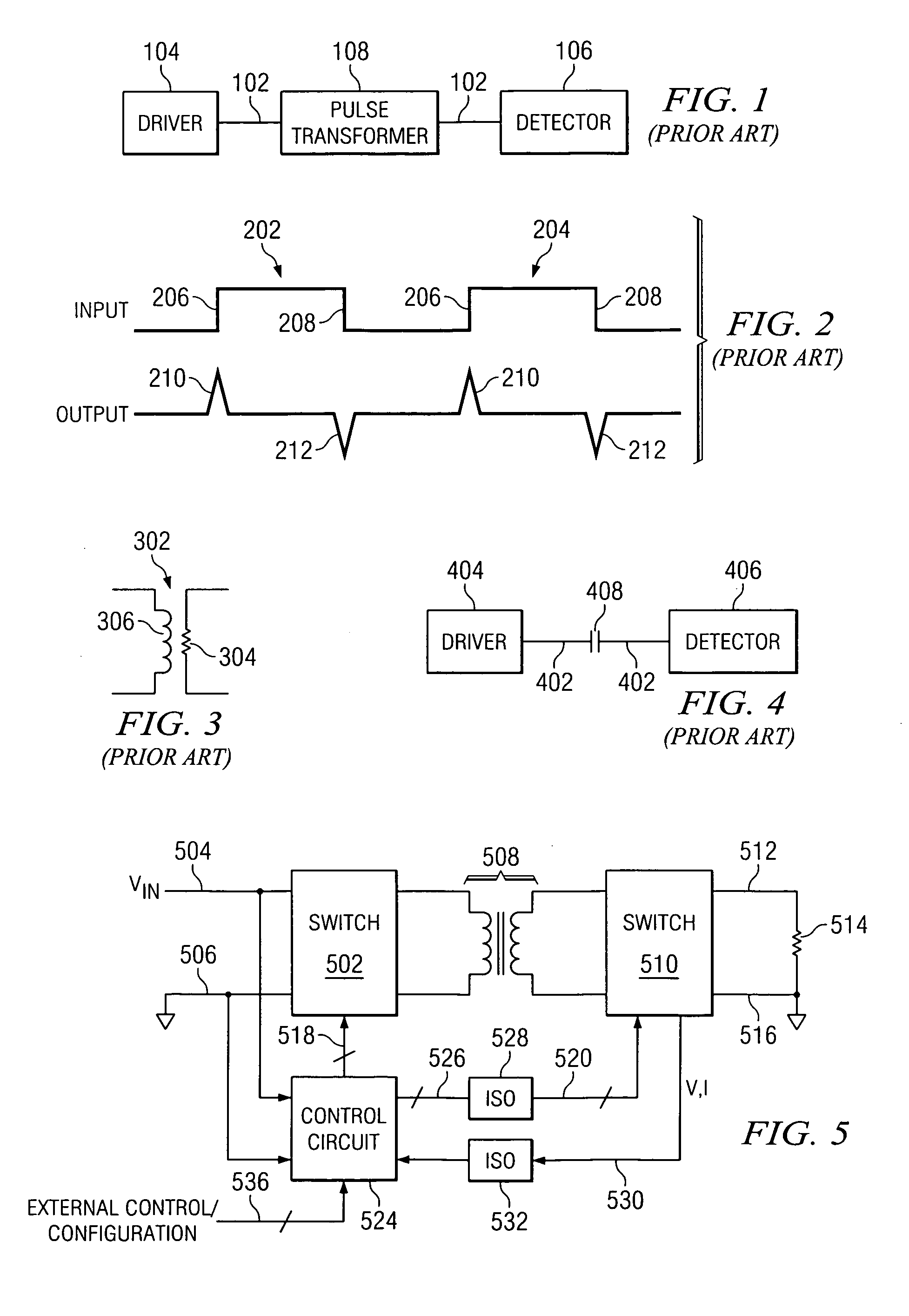
[0078]Referring now to the drawings, and more particularly to FIG. 5, there is illustrated a block diagram of a DC-DC switching power supply utilizing an RF isolation link. Switching power supplies utilize a plurality of switches which are turned on and off to switch an input DC voltage across a transformer to a load, the output voltage at a different DC voltage level. By switching the current inductively coupled through the transformer to the load in a particular manner, a DC output voltage at a different voltage level than the input DC voltage can be provided to the load. The controlled switching is typically facilitated with some type of control circuit. This control circuit can be an analog control circuit formed from a plurality of analog discrete devices, or it can be a digital circuit. In digital control circuits, digital signal processors (DSPs) and microcontroller units (MCU) have been utilized. The DSPs control the duty cycle and relative timing of the switches such that t...


PUM


Abstract

A circuit package includes first and second units containing functional circuitry. At least one RF isolation link interconnects the first and second units and provides voltage isolation between the first and second units. The RF isolation link provides data between the first unit and the second unit using an RF carrier signal that sweeps between a first frequency and a second frequency.

Description

CROSS-REFERENCE TO RELATED APPLICATIONS[0001]This application is a continuation-in-part of co-pending U.S. application Ser. No. 10 / 860,399 filed on Jun. 3, 2004 entitled Transformer Isolator for Digital Power Supply, co-pending U.S. application Ser. No. 10 / 860,519 filed on Jun. 3, 2004 entitled On-Chip Transformer Isolator, co-pending U.S. application Ser. No. 11 / 020,977 filed on Dec. 22, 2004 entitled RF Isolator with Differential Input / Output and co-pending U.S. patent application Ser. No. 11 / 064,413 filed on Feb. 23, 2005 entitled RF Isolator for Isolating Voltage Sensing and Gate Drivers.TECHNICAL FIELD OF THE INVENTION[0002]The present invention relates to digital isolators, and more particularly, to digital isolators providing isolation for voltage sensing and gate drivers.BACKGROUND OF THE INVENTION[0003]Within power conversion products, there is a need for high speed digital links that provide high isolation at a low cost. Typical digital links within power conversion produc...

Claims


Application Information

Patent Timeline
Patent Type & Authority Patents(United States)
IPC IPC(8): H04B1/18H04B1/16H01L23/66H02M3/335H04B3/00
CPCH01L23/66H01L24/06H01L24/49H04L25/0266H01L23/49503H01L2224/48247H01L23/49575H01L2224/48095H01L2224/48137H01L2224/49171H01L2224/49175H01L2924/01004H01L2924/01005H01L2924/01014H01L2924/01015H01L2924/01027H01L2924/01082H01L2924/13055H01L2924/13091H01L2924/14H01L2924/19041H01L2924/19042H01L2924/19043H01L2924/30105H01L2924/30107H01L2924/3011H01L2924/3025H01L23/4952H01L2924/12041H01L2924/01033H01L2924/01023H01L24/48H01L2924/00014H01L2924/00H01L2224/05554H01L2924/1204H02M3/33523H01L2224/45099H01L2224/05599
Inventor DUPUIS, TIMOTHY
Owner SKYWORKS SOLUTIONS INC
Why Eureka
Try Eureka