Methods and apparatus providing remote monitoring of security and video systems

a technology for video systems and remote monitoring, applied in the field of methods and equipment providing remote monitoring of security and video systems, can solve the problems of large security problems at the protected site, the same amount of bandwidth, and the suffering of conventional security and monitoring systems

Inactive Publication Date: 2007-11-27
RADIA TECH CORP
View PDF7 Cites 81 Cited by
  • Summary
  • Abstract
  • Description
  • Claims
  • Application Information

AI Technical Summary

Benefits of technology

[0008]If the bandwidth required to transmit video, audio and alarm data for an event to one remote monitoring station endpoint is N kilobits per second (kbps) and the number of remote endpoints that are required to receive this information is P, then the total bandwidth required to transmit the information for an event to all endpoints is P*N. An average medium level performance DSL or Cable modem line for a typical home or business has approximately enough bandwidth for a video transmission with a sufficient picture size, frame rate and video quality to recognize people and objects in the video data with sufficient clarity. This bandwidth corresponds to the N kbps for transmission method 1. However the real bandwidth need for P endpoints is P*N, which is correspondingly P times the bandwidth most installations are currently able to provide in practical settings. Thus, a conventional implementation of method 1 requires a limitation of a single monitoring station endpoint and / or requires an Internet connection with substantially more than an average amount of bandwidth. Although this additional bandwidth can be provided, it substantially increases the cost of maintaining and operating the protected site system.
[0025]This secondary or client responder site can then prepare and forward a bookmark playback request to the event processor within the proxy site and can receive, in response, the segment of event data associated with the bookmark notification to allow that client responder site to access the segment of video data identified by the bookmark work item received from the primary monitor responder site. In this manner, embodiments of the invention allow two or more responder sites to notify each other of event data that may be of interest that provides for enhanced security and protection measures with respect to protecting the protected site.

Problems solved by technology

Conventional security and monitoring systems suffer from a variety of deficiencies.
Although current conventional security and monitoring systems support the basic requirement of conveying event and alarm information from one location to another over a computer network, the manner in which this is done creates substantial security problems at the protected site.
While this method maintains a high level of security, it requires the same amount of bandwidth for each monitoring station endpoint to and from the protected site.
Thus, a conventional implementation of method 1 requires a limitation of a single monitoring station endpoint and / or requires an Internet connection with substantially more than an average amount of bandwidth.
Although this additional bandwidth can be provided, it substantially increases the cost of maintaining and operating the protected site system.
Although this solves the bandwidth problem it creates a substantial security issue and also suffers from a number of other deficiencies.
Since the Internet itself is not a secure protocol the proper routing of such packets using only IP cannot be ensured.
In addition, since the same packets are shipped to each endpoint there is no possibility of independently verifying the authenticity of endpoints individually and encryption of such data becomes problematic due to a requirement to have many endpoints share common key material used for decryption.

Method used


Image

  • Methods and apparatus providing remote monitoring of security and video systems
  • Methods and apparatus providing remote monitoring of security and video systems
  • Methods and apparatus providing remote monitoring of security and video systems

Examples


Embodiment Construction

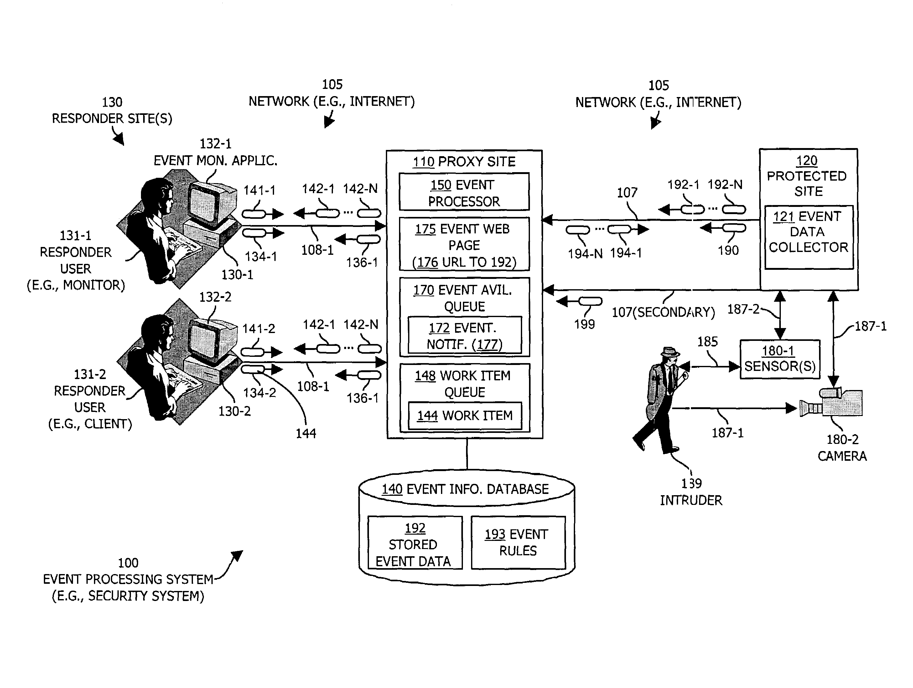
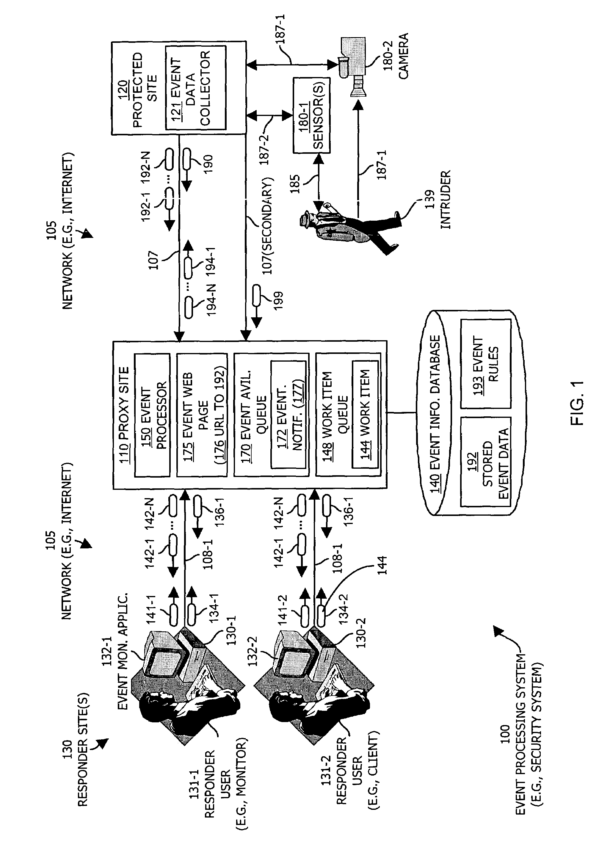
[0040]FIG. 1 illustrates an event processing system 100 configured in accordance with one example embodiment of the invention. The event processing system 100 in FIG. 1 includes a communications medium 105 such as a computer network medium (e.g., a wide area network such as the Internet) that interconnects a proxy site 110, a protected site 120 and one or more responder sites 130 (130-1 and 130-2 in this example). The protected site 120, proxy site 110 and responder sites 130 may each be, for example, computer systems.

[0041]The proxy site 110 includes an associated event information database 140 that maintains stored event data 192 (as will be explained) and is further configured to operate an event processor 150. The proxy site 110 in this example also includes an event availability queue 170 and an event web page 175, the purposes of which will be explained shortly.

[0042]The protected site 120 operates an event data collector 121 (as will be explained) and further includes in inte...


PUM


Abstract

A security system includes a proxy site that interconnects a protected site and one or more responder sites using a computer network. The protected site operates an event data collector coupled to sensors that when activated, produce event data. The event data collector can initiate connections with an event processor in the proxy site to transmit the event data to the proxy site for access by one or more of the responder sites. The event processor can receive and store the event data and can provide notifications to the responder sites of the stored event data. The responder sites can periodically poll the proxy site and can receive responses that reference available event data associated with those responder sites. The system allows responder sites share references to event data, and allows the event processor to use event rules to notify different responder sites in different manners according to different event types.

Description

PRIORITY TO PROVISIONAL PATENT APPLICATION[0001]This application for patent claims the benefit of the filing date of formerly filed, co-pending, United States Provisional Application for Patent entitled “METHODS AND APPARATUS PROVIDING REMOTE MONITORING OF SECURITY AND VIDEO SYSTEMS”, having U.S. Ser. 60 / 371,856, filed Apr. 11, 2002 and assigned to the same Assignee as the present invention. The entire teachings, disclosure and contents of this referenced provisional patent application are hereby incorporated by reference herein in their entirety.BACKGROUND OF THE INVENTION[0002]Conventional security and monitoring systems allow a central monitoring station to receive alarm information concerning events that occur in a remote protected area. Such systems allow an operator of the monitoring station to monitor the status of sensors within the protected area and upon the occurrence of an event that triggers a sensor, conventional systems allow the operator to interact with other device...

Claims


Application Information

Patent Timeline
Patent Type & Authority Patents(United States)
IPC IPC(8): G06F15/177
CPCH04L63/0281H04L69/163H04L69/16H04L63/08
Inventor WILSON, RANDY S.
Owner RADIA TECH CORP
Why Eureka
Try Eureka