
Oscillation generating device

a generation device and oscillator technology, applied in the direction of mechanical vibration separation, gearing, ways, etc., can solve the problems of unbalanced two-shaft rotation synchronously, unsatisfactory tipping moment, and application of centrifugal force of two-shaft unbalance shafts. , to achieve the effect of economic advantages and even further simplified synchronization

Inactive Publication Date: 2007-12-04
BOMAG +1
View PDF11 Cites 6 Cited by
  • Summary
  • Abstract
  • Description
  • Claims
  • Application Information

AI Technical Summary

Benefits of technology

[0008]Another advantage of the invention is the fact that the oscillation generator is constructed in a simple and symmetrical manner of similar components, so that economic advantages are achieved. Since the entire unbalance mass is distributed on four shafts, the entire unbalance mass can be increased, or the unbalance shafts can be given smaller dimensions.
[0009]The unbalance shafts do not have to lie adjacent to each other aligned in pairs, but rather the unbalance shafts of the one unbalance shaft pair can be offset with crosswise symmetry axially parallel to the unbalance shafts of the other unbalance shaft pair. The term “crosswise symmetry” denotes an arrangement here in which the diagonally opposite unbalance shafts are arranged in pairs symmetrically with respect to the point of intersection of their connecting lines.
[0010]The axially parallel offset can take place within the same plane or out of the plane. For example, a rear left unbalance shaft could be offset upward by a certain amount. The front right unbalance shaft would then have to be offset downward by the same amount in order to establish the required symmetry. It can also be advantageous in this instance for the spacings of the diagonally opposite unbalance shafts to be different.
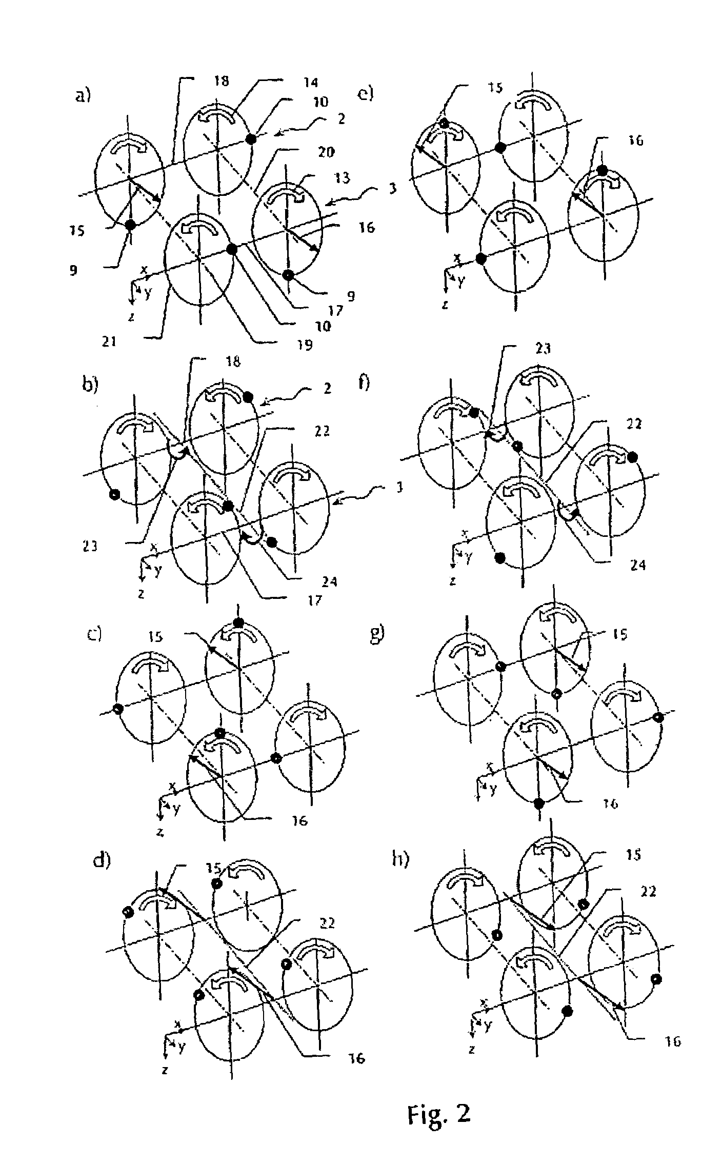
[0011]There is the possibility in the device of the invention of producing a steering movement by changing the phase relation of an unbalance shaft.
[0012]The diagonal unbalance shafts can basically be driven separately. The diagonal unbalance shafts are preferably coupled in such a manner that they rotate in unison. e.g., via a transmission. This has the advantage that the diagonal unbalance shafts always retain the same direction of rotation and the same speed of rotation, which always guarantees functionality as well as the compensation of tipping moments. The synchronization is even further simplified by virtue of the fact that all unbalance shafts are coupled such that they rotate in unison.
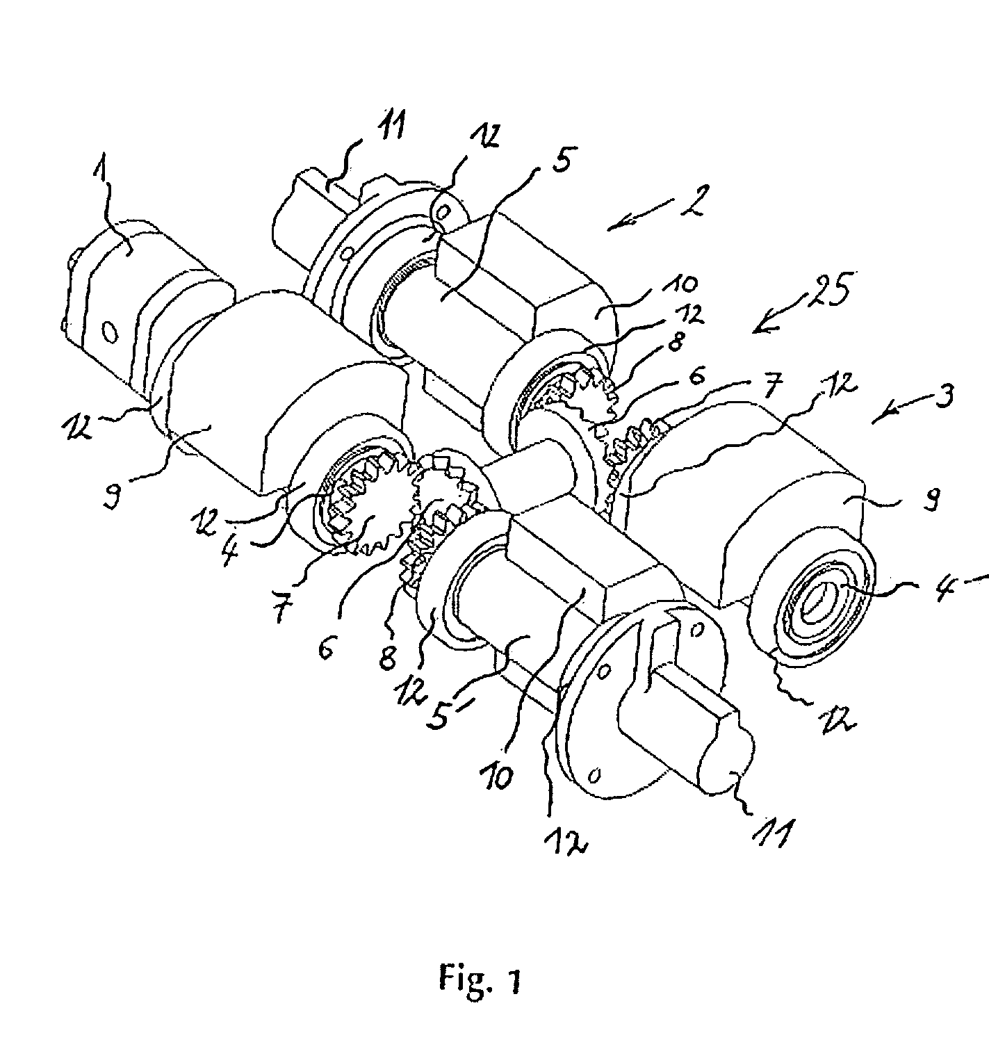
[0013]In an advantageous embodiment, the transmission comprises two connected crown gears, and spur gears on the unbalance shafts engaging with them. This has the advantage that a transmission which guarantees the function of the device is created from relatively few simple and known components.

Problems solved by technology

The unbalances of the two shafts rotate synchronously but with the opposite directions of rotation.
As a consequence, the resulting centrifugal force of two unbalance shafts always is applied at another point during the course of a rotation.
This tipping moment is undesirable because it has a disadvantageous effect on the behavior of the movement of the soil compacter.
The unbalance mass of the central unbalance shaft is as great as the entire unbalance mass of the pair of unbalanced shafts.

Method used


Image

  • Oscillation generating device
  • Oscillation generating device
  • Oscillation generating device

Examples


Embodiment Construction

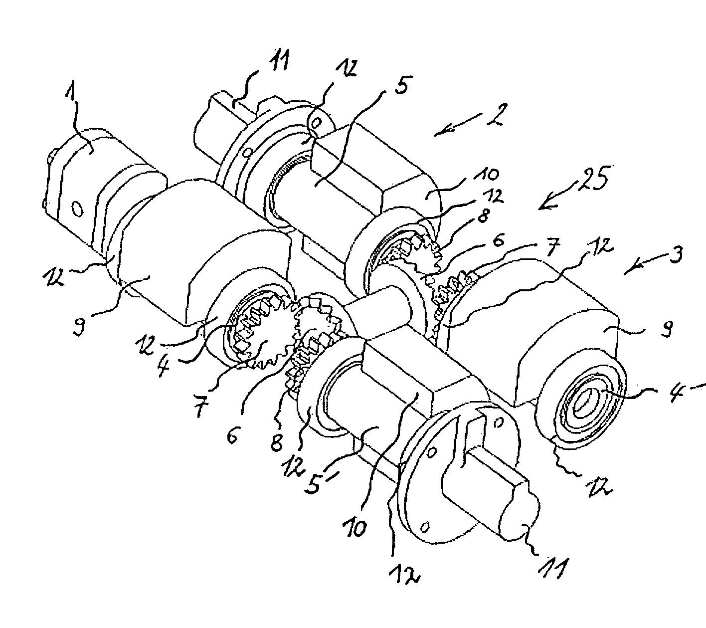
[0021]FIG. 1 shows in detail a first soil compacter oscillation generating device driven by drive 1, wherein, parallel to, and laterally offset in the axial direction from, a first unbalance shaft pair 2 is arranged a second, similar unbalance shaft pair 3 as a tipping moment compensation device.

[0022]Each unbalance pair 2, 3 comprises two tandem and axially parallel unbalance shafts 4, 5 and 4′, 5′ that rotate in opposite directions with the same unbalance masses 9, 10. Unbalance masses 9, 10 of an unbalance shaft pair 2, 3 are offset at an angle in order to produce phase-shifted centrifugal forces. Unbalance shaft pairs 2,3 are located adjacent to each other in such a manner that their unbalance shafts are aligned in pairs. Furthermore, unbalance shafts with the same direction of rotation are located diagonally opposite each other. Unbalance shafts 4, 4′ rotating in the same direction on the one hand and unbalance shafts 5, 5′ rotating in opposite directions on the other hand have...


PUM


Abstract

The invention relates to an oscillation generating device for use in a soil compacter with a tipping moment compensation device. A second unbalance shaft pair with oppositely rotating unbalance shafts is arranged adjacent to a first unbalance shaft pair as a tipping moment compensation device. Diagonally opposite unbalance shafts rotate in the same direction. In this way, centrifugal forces and torques on the two unbalance shaft pairs reciprocally cancel each other out so that no tipping moment occurs parallel to the axes of rotation of the unbalances.

Description

FIELD OF THE INVENTION[0001]The invention relates to an oscillation generating device for use in a soil compacter such as, e.g., a vibratory plate or a roller, with an oscillation generating device, a first unbalance shaft pair, and a tipping moment compensation device.BACKGROUND OF THE INVENTION[0002]Traditional soil compacters, e.g., reversible vibration plates and vibration rollers, are equipped with a contrarotating unbalance shaft pair for generating directed oscillations. The unbalances of the two shafts rotate synchronously but with the opposite directions of rotation. A desired, directed direction of oscillation can be adjusted by phase shifting, and a directed forward or reverse movement of the soil compacter can be produced.[0003]However, a periodically changing tipping moment is produced as a function of the phase position of the unbalances. This tipping moment occurs because the individual unbalances have different axes of rotation. As a consequence, the resulting centri...

Claims


Application Information

Patent Timeline
Patent Type & Authority Patents(United States)
IPC IPC(8): F16H33/10B06B1/16E02D3/074
CPCB06B1/16E02D3/074Y10T74/18544Y10T74/18552Y10S37/903
Inventor LAUGWITZ, NIELS
Owner BOMAG
Learn More