
Air conditioning unit for motor vehicles and method for its operation

a technology for air conditioning units and motor vehicles, applied in the direction of subcoolers, domestic cooling devices, lighting and heating devices, etc., can solve the problems of insufficient cooling effect, hence refrigeration capacity, inability to achieve optimal high pressure or the necessary refrigeration capacity, and difficulty in making such an approximation to ambient temperatur

Active Publication Date: 2009-01-22
HANON SYST
View PDF27 Cites 33 Cited by
  • Summary
  • Abstract
  • Description
  • Claims
  • Application Information

AI Technical Summary

Benefits of technology

[0016]Automated operation of an air conditioning unit according to the invention can, for example, be obtained by that the temperature of the refrigerant is automatically reduced when the value of the measured parameter exceeds a threshold value. It is particularly advantageous if hereby the temperature of the refrigerant is reduced in a controlled manner, whereby the measured parameter is used as control variable. That means that the additional heat sink is not simply activated, but the energy required for the activation of the heat sink is continuously utilized according to the demand, not being wasted by a too high cooling output.
[0018]Ecological and economical advantages follow because the components of the compression refrigeration circuit of air conditioning units according to the invention can be dimensioned closer to the rating due to the switchable power reserves and less energy is needed to operate the air conditioning unit under optimal and normal ambient conditions.

Problems solved by technology

In many vehicles, it is difficult to make such an approximation to the ambient temperature, particularly during a halt of the vehicle or under unfavorable ambient conditions.
Even if the temperature of the refrigerant was lowered to the temperature of this relatively hot cooling air, which is virtually impossible by mere heat transfer, the resulting cooling effect, hence the refrigeration capacity, would be insufficient in many cases.
As a consequence, depending on the circuit design, the optimal high pressure or the necessary refrigeration capacity, respectively, can no longer be realized.
A decrease in the COP and an increase in the power demand of the compressor drive result.
In particular, at high ambient temperatures, where a high refrigeration capacity is normally required, these effects are markedly negative, not compatible with the comfort demands as having become usual in the meantime.
However, such a design places relatively high installation demands for the realization of the various flow paths and the great number of line connections.
However, the problem of a too high ambient temperature as the lowest theoretically achievable refrigerant temperature at the outlet of the heat-delivering heat exchanger remains unsolved with this solution.
This solution is disadvantageous in that the formation of condensate and the efficiency of the evaporation strongly depend on the ambient conditions, particularly the humidity of the air.
Hence the supporting function of such an assembly can only be controlled within narrow limits.

Method used


Image

  • Air conditioning unit for motor vehicles and method for its operation
  • Air conditioning unit for motor vehicles and method for its operation
  • Air conditioning unit for motor vehicles and method for its operation

Examples


Embodiment Construction

[0035]The following detailed description and appended drawings describe and illustrate various embodiments of the invention. The description and drawings serve to enable one skilled in the art to make and use the invention, and are not intended to limit the scope of the invention in any manner. In respect of the methods disclosed, the steps presented are exemplary in nature, and thus, the order of the steps is not necessary or critical.

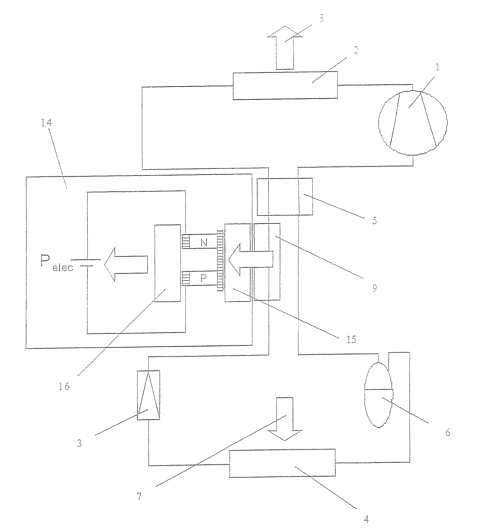
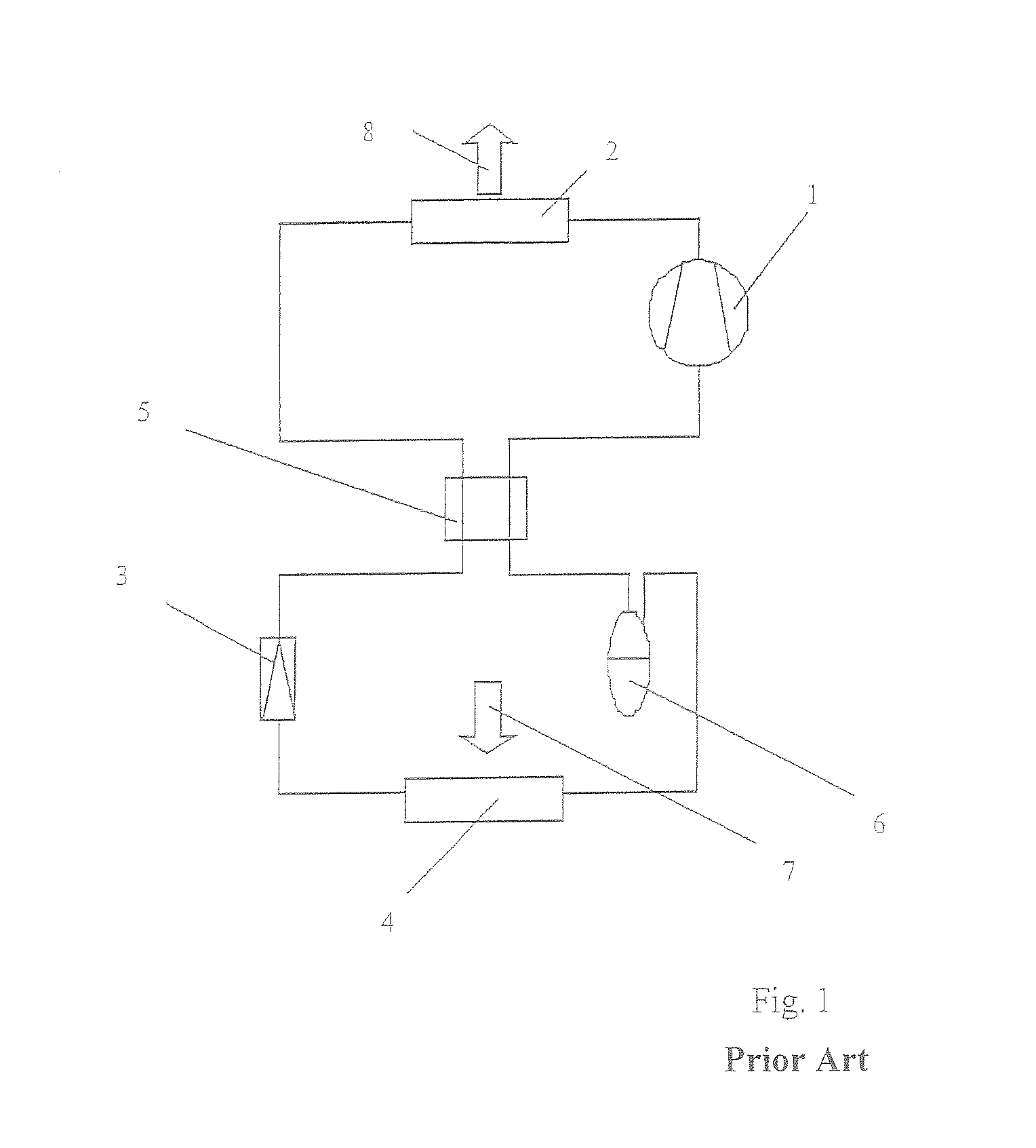
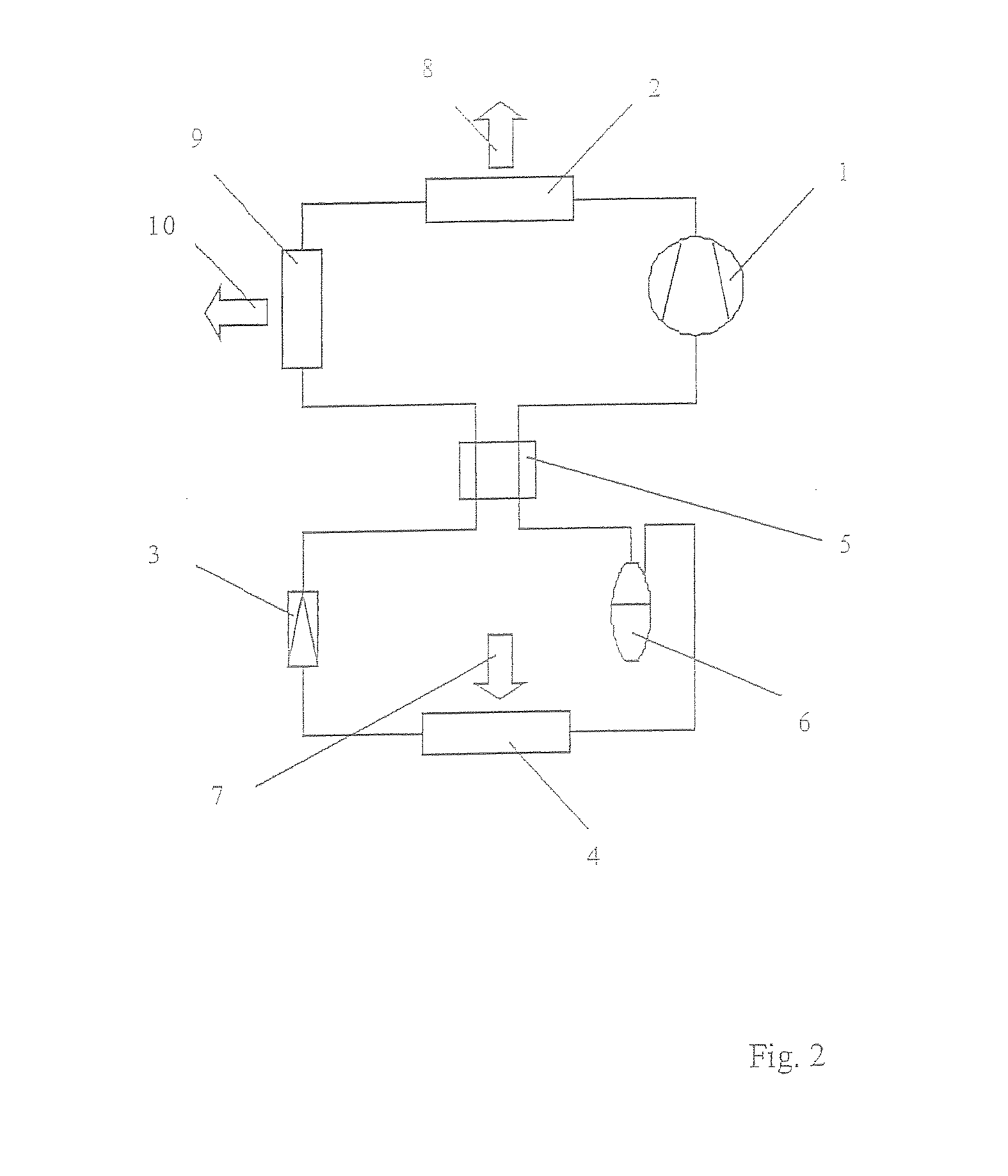
[0036]FIG. 1 shows a conventional compression refrigeration circuit of an air conditioning unit for motor vehicles. This circuit includes a compressor 1, a heat-delivering heat exchanger 2, i. e. a heat exchanger in form of a condenser, or gas cooler, respectively, an expansion element 3, and a heat-absorbing heat exchanger 4, for example in form of an evaporator. During operation of the air conditioning unit, a refrigerant circulates in the compression refrigeration circuit, the refrigerant continuously changing its temperature and / or pressure with p...


PUM


Abstract

An air conditioning unit is disclosed for motor vehicles. The air conditioning unit includes with a compression refrigerant circuit where a refrigerant circulates, comprising comprehensively switched in series with respect to fluid flow at least one compressor upstream of a heat-delivering heat exchanger, and an expansion element upstream of a heat-absorbing heat exchanger, whereby into the flow path leading from the outlet of the heat-delivering heat exchanger to the expansion element an additional heat exchanger is integrated thermally coupled to at least one cooling means the temperature of which can be put to values below the temperature of the refrigerant in the compression refrigeration circuit at the position of the refrigerant's outflow from the heat-delivering heat exchanger, and a method for its operation.

Description

CROSS-REFERENCE TO RELATED APPLICATION[0001]This application claims the benefit of German patent application serial no. DE 102007035110.2-16 filed Jul. 20, 2007, hereby incorporated herein by reference in its entirety.FIELD OF THE INVENTION[0002]The present invention relates to an air conditioning unit for motor vehicles, and more specifically to a compression refrigerant circuit of an air conditioning unit for motor vehicles.BACKGROUND OF THE INVENTION[0003]Air conditioning units for motor vehicles typically include a compressor, a heat exchanger delivering heat, i. e. a condenser, or gas cooler, respectively, an expansion element, and one or several heat exchangers absorbing heat, for example evaporators. The heat-delivering heat exchanger functions to cool the refrigerant after having been compressed and heated as close as possible to the ambient temperature level. The heat-delivering heat exchanger is typically positioned in the engine compartment between the head lamps exposed ...

Claims


Application Information

Patent Timeline
IPC IPC(8): F25B21/02F25B25/02
CPCB60H1/005B60H1/3208B60H1/323B60H2001/3289F25B40/02F25B7/00F25B9/008F25B21/02B60H2001/3291
Inventor HECKT, ROMANGRAAF, MARCHAAS, TOBIAS
Owner HANON SYST
Learn More