Concrete form with keyway and clamp with base engaging the keyway

a technology of concrete form and keyway, which is applied in the direction of forms/shuttering/falseworks, artificial islands, excavations, etc., can solve the problem of premature wear out of the base corners

Inactive Publication Date: 2007-12-04
LANE MICHAEL
View PDF5 Cites 26 Cited by
  • Summary
  • Abstract
  • Description
  • Claims
  • Application Information

AI Technical Summary

Benefits of technology

[0009]Preferably, the clamp base matches the keyway. That is, a base vertical, or narrow, dimension is of dimension such that it passes easily into the keyway. The keyway has a dimension between the keyway sides. Preferably, the base horizontal dimension is less than or equal to the keyway dimension between its sides. Preferably, the base has rounded corners so the base can be rotated in the keyway without binding. Thus, when the base inserted in the keyway is rotated up to 90 degrees the base rotates into locking position partially behind the keyway front wall without binding in or distorting the keyway. A stop is provided on the base to prevent rotation of the base beyond its locking position. The concrete form further has at least one brace wall extending between intermediate the keyway back wall to the form back. Preferably the form has two brace walls near but spaced apart from keyway sides to strengthen the keyway.

Problems solved by technology

The resistance through the base corners against the keyway during rotation is effective but tends to wear out the base corners prematurely.

Method used


Image

  • Concrete form with keyway and clamp with base engaging the keyway
  • Concrete form with keyway and clamp with base engaging the keyway
  • Concrete form with keyway and clamp with base engaging the keyway

Examples


Embodiment Construction

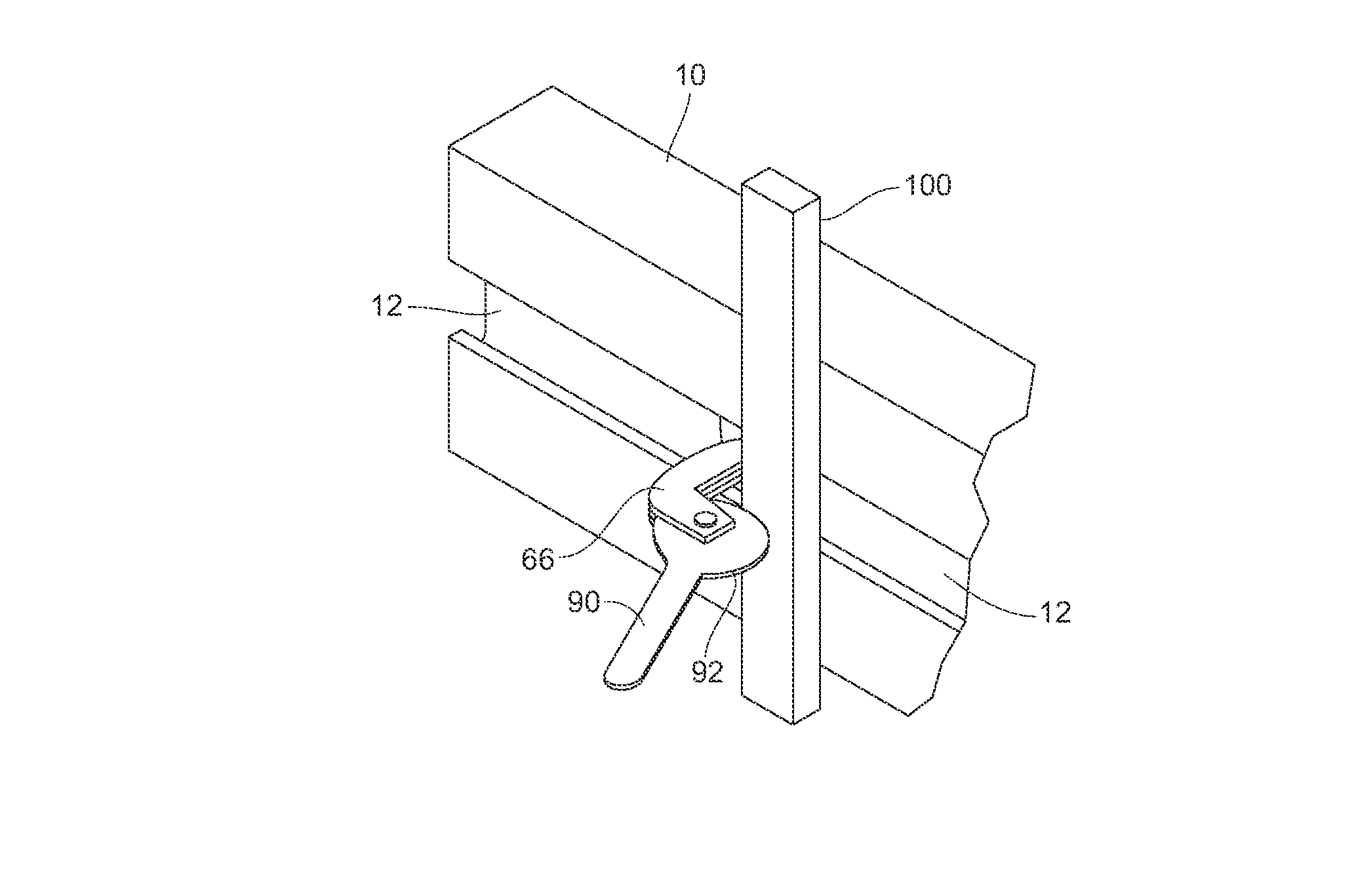
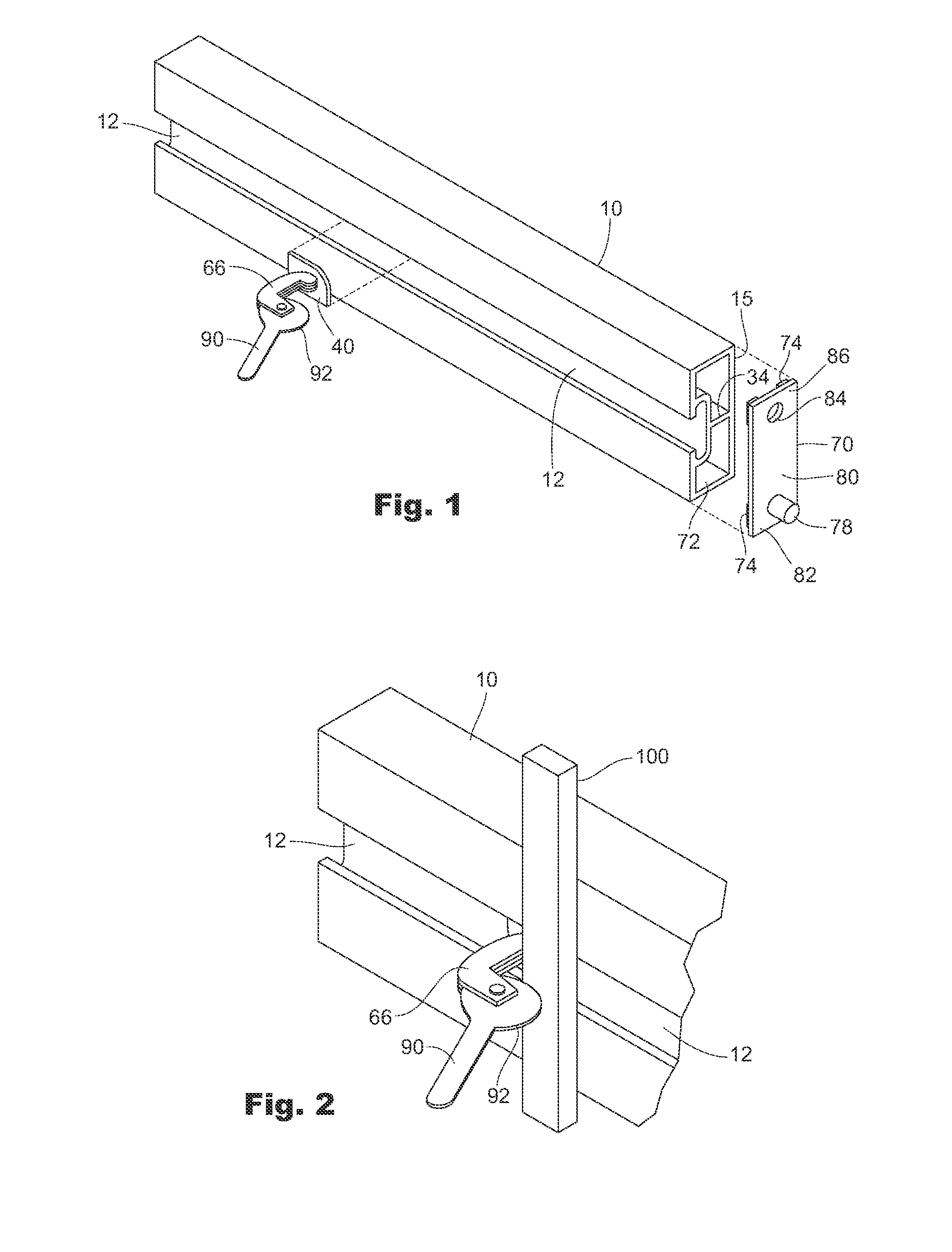
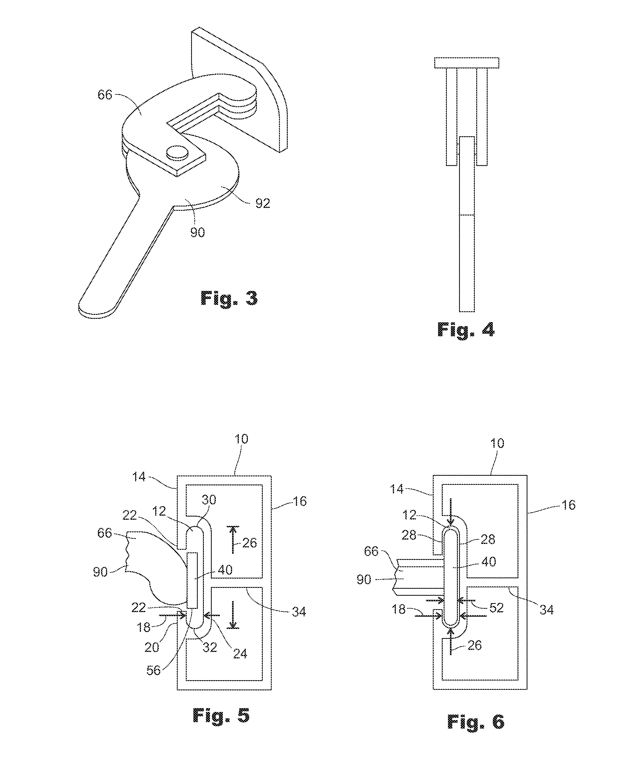
[0024]An elongate concrete form 10 primarily of polyethylene plastic material generally in the shape of a plank of lumber comprises a keyway 12 on a form front side 14 opposite a back side 16. The keyway 12 has a width 18 between a keyway front 20 with opposing lips 22, a keyway back 24, and a height 26 orthogonal to its width 18, and the opening as an entrance into the keyway 12 between the opposing lips 22. The keyway front 20 and back 24 are generally parallel or have parallel portions 28, recognizing that the keyway top 30 and bottom 32 may be curved, in which case the front 20 will be a mirror image of an opposing portion of the back 24 and the parallel portions 28 are the lips 22 and the back 24. For purposes herein, the distinction is irrelevant and reference to front and back parallel portions 22 and 24 is meant to include a curved keyway top and bottom 30, 32. The concrete form 10 also includes at least one dividing wall 34 to strengthen the form 10. The concrete form 10 ma...


PUM

PropertyMeasurementUnit
Angleaaaaaaaaaa
Angleaaaaaaaaaa
Sizeaaaaaaaaaa

Abstract

A concrete form with a keyway with an opening between opposing keyway lips together with a base that fits through the keyway opening and rotates without restriction in the keyway such that a portion of the base rests behind the keyway lips so when it is pulled as a clamp or tie is exercised to secure a stake to the form the base is secured tight against the form front. The concrete form further has at least one brace wall extending between intermediate the keyway back wall and the form back. Form end connectors securable in form ends are provided that join two forms aligned end to end.

Description

BACKGROUND[0001]1. Field of the Invention[0002]This invention relates to construction forms for installing concrete, and more particularly, to a polyethylene concrete form with a keyway that receives a base of a clamp that locks the concrete form to a stake and also relates to a concrete form end connector.[0003]2. Prior Art[0004]Concrete forms form the retaining walls between which concrete is poured and held until the concrete sufficiently hardens for the forms to be removed. The concrete forms are historically made of wood or steel and more recently of extruded polyethylene as well documented by Pawlicki in U.S. Pat. No. 5,015,117 issued in 1991. Where wood could be reused only a few times, extruded polyethylene forms can be used repeatedly for years and, unlike steel forms, they are lightweight for ease in transporting them.[0005]The polyethylene concrete form described by Pawlicki further included a dovetailed keyway in a side into which is received a base of a clamp that secur...

Claims


Application Information

Patent Timeline
IPC IPC(8): E04G9/10
CPCE04G9/05E04G17/02E04G13/00
Inventor LANE, MICHAEL
Owner LANE MICHAEL
Why Eureka
Try Eureka