Electrical connecting member capable of achieving stable connection with a simple structure and connector using the same

a technology of electrical connecting member and simple structure, which is applied in the direction of elastomeric connecting element apparatus, electrical apparatus construction details, and semiconductor/solid-state device details, etc., can solve the problems of poor retryability of electrical connecting member, poor mass-productivity of electrical connector, and inability to adapt easily, so as to achieve easy retryability, reduce the size of the electrical connector, and increase the number of contacts

Inactive Publication Date: 2007-12-04
JAPAN AVIATION ELECTRONICS IND LTD
View PDF26 Cites 14 Cited by
  • Summary
  • Abstract
  • Description
  • Claims
  • Application Information

AI Technical Summary

Benefits of technology

[0008]It is another object of this invention to provide an electrical connecting member and a connector which can easily be reduced in size, increased in number of contacts, and narrowed in pitch within a limited space.

Problems solved by technology

However, this electrical connector is not excellent in mass-productivity and is not easily adaptable to the increase in number of contacts because the balls are embedded in the resin film one by one.
However, this electrical connecting member is poor in retryability because, upon occurrence of an error in a step of setting the conductive fibers, not only the conductive fibers but also the insulating sheet with pierced holes formed therein by setting the conductive fibers must be discarded.
However, this connector is disadvantageous in that the contact is less compliant with a terminal of a substrate as a connection object.

Method used


Image

  • Electrical connecting member capable of achieving stable connection with a simple structure and connector using the same
  • Electrical connecting member capable of achieving stable connection with a simple structure and connector using the same
  • Electrical connecting member capable of achieving stable connection with a simple structure and connector using the same

Examples


first embodiment

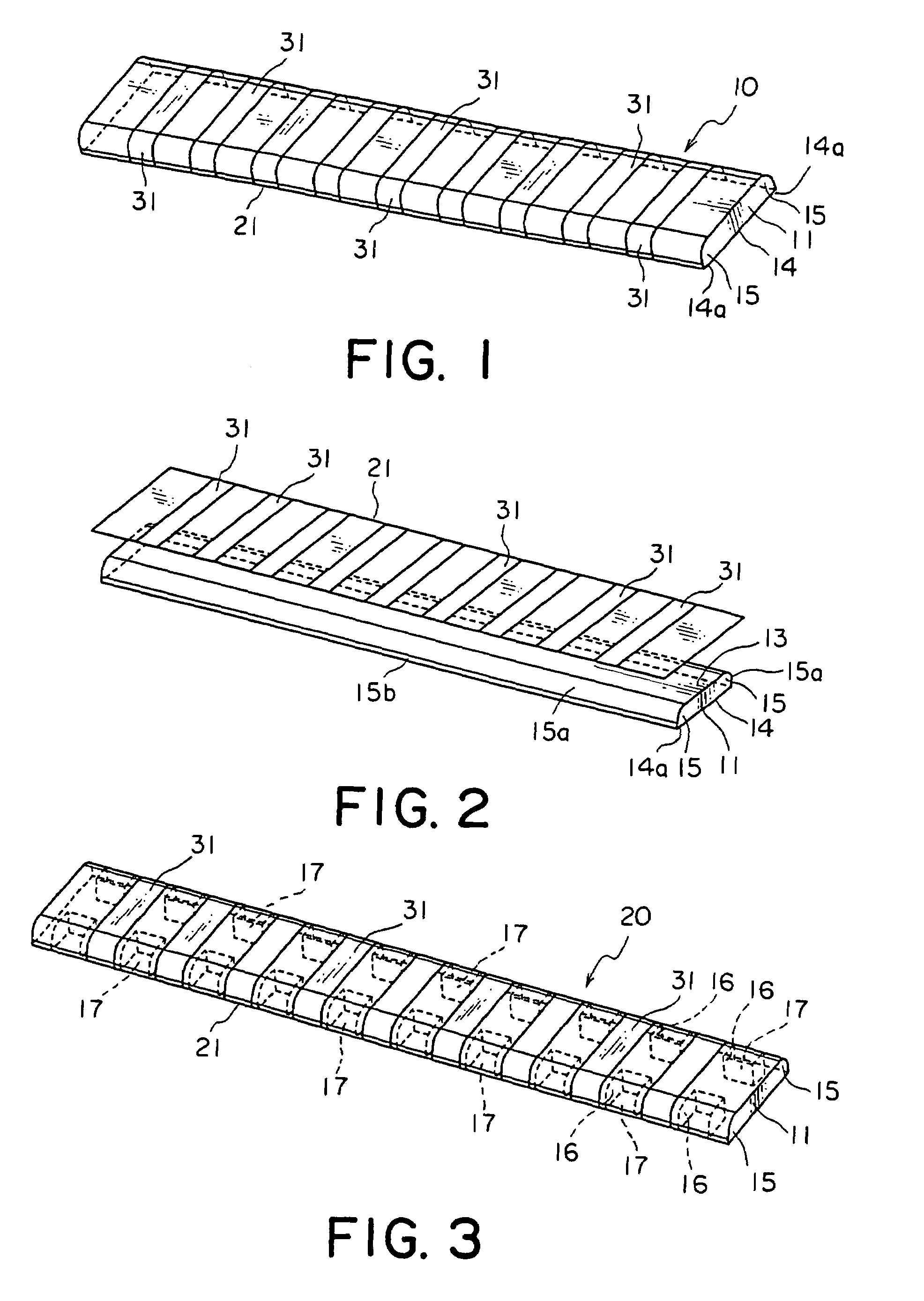
[0028]Referring to FIGS. 1 and 2, description will be made of an electrical connecting member according to this invention.

[0029]In FIGS. 1 and 2, the electrical connecting member 10 comprises an elastic body 11, an insulating film 21 held by the elastic body 11, and a plurality of conductor portions 31 formed on the film 21. The elastic body 11 has a generally rectangular plate-like shape and has a holding surface 13 holding the film 21 and a flat base surface 14 opposite to the holding surface 13. The conductor portions 31 are disposed on a surface of the film 21 on a side opposite to the holding surface 13.

[0030]The elastic body 11 has a pair of protruding portions 15 protruding from opposite sides in a widthwise direction perpendicular to a longitudinal direction, respectively. Each of the protruding portions 15 has a protruding base surface 14a of a flat shape extending from the base surface 14, a curved surface 15a formed as a generally cylindrical surface protruding from the h...

second embodiment

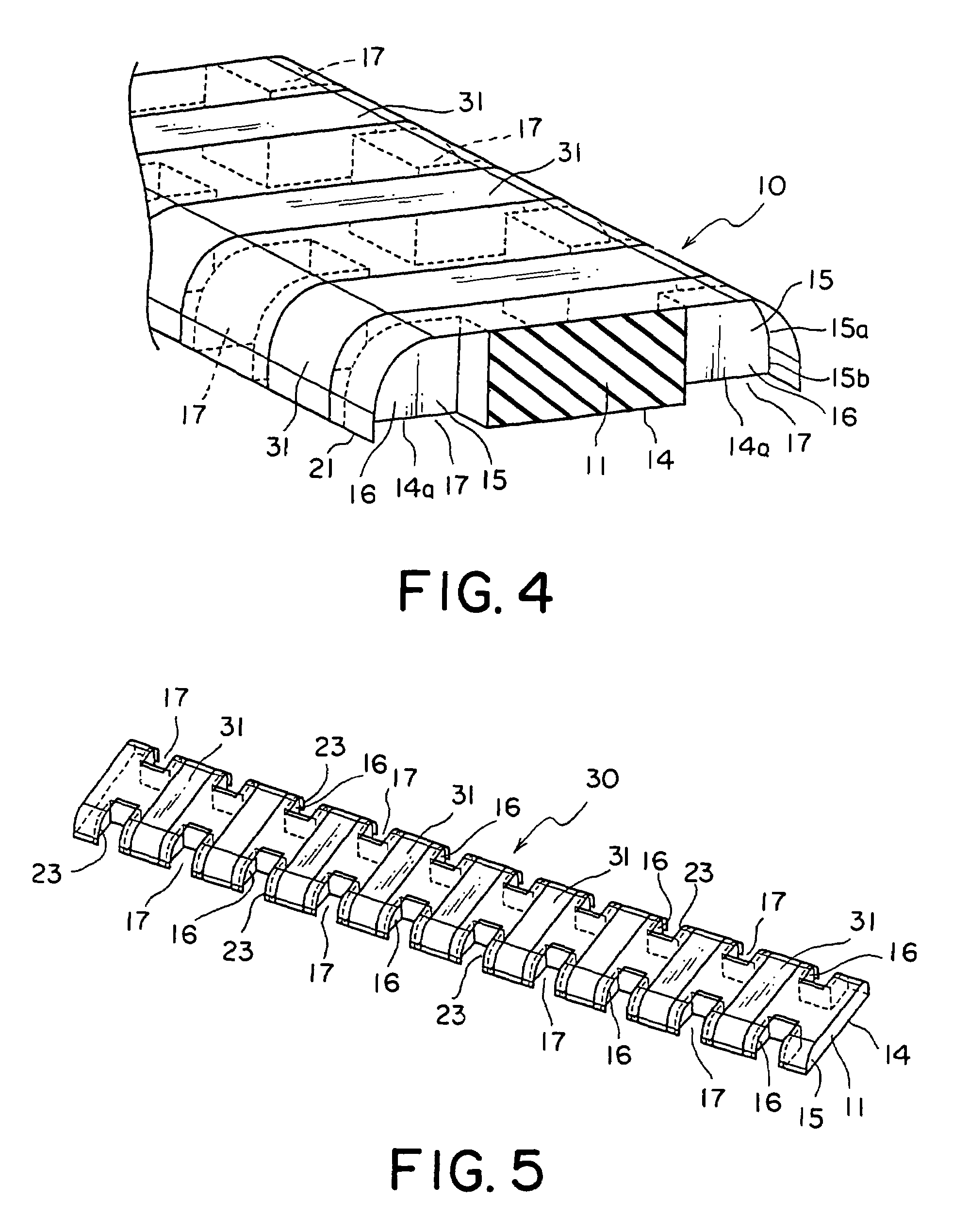
[0036]Referring to FIGS. 3 and 4, description will be made of an electrical connecting member according to this invention. Similar parts to those of the electrical connecting member 10 illustrated in FIGS. 1 and 2 are designated by like reference numerals and description thereof will be omitted.

[0037]In the electrical connecting member 20 in FIGS. 3 and 4, the elastic member 11 has a plurality of grooves 17 formed on the protruding portions 15. Consequently, each of the protruding portions 15 is divided into a plurality of projections 16 separated by the grooves 17 from one another. In other words, each groove 17 is positioned between adjacent ones of the projections 16. Each projection 16 is defined by the grooves 17, the curved surface 15a, the side surface 15b, and the protruding base surface 14a.

[0038]The grooves 17 formed in the elastic body 11 serve as a relief space for the elastic member 11 when the elastic member 11 is compressed and deformed in the widthwise direction. Th...

third embodiment

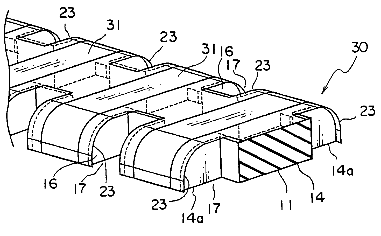
[0040]Referring to FIGS. 5 and 6, description will be made of an electrical connecting member according to this invention. Similar parts to those of the electrical connecting member 20 illustrated in FIGS. 3 and 4 are designated by like reference numerals and description thereof will be omitted.

[0041]In the electrical connecting member 30 illustrated in FIGS. 5 and 6, a film 21 has a plurality of cutout portions 23 formed by cutting those parts faced to the grooves 17 of the elastic member 11. By forming the cutout portions 23 in the film 21, each part of the elastic member 11 between adjacent conductor portions 31 can independently be deformed. Therefore, with respect to distortion or warping of the connection object as well as a slight difference in height of the conductor portions 31, it is possible to achieve stable connection at the level of the conductor portions 31.

[0042]Next referring to FIGS. 7 and 8, description will be made of a first example of a connector using the elec...


PUM


Abstract

In an electrical connecting member for electrical connection with a connection object, the electrical connecting member includes an elastic body having a pair of protruding portions protruding in directions opposite to each other. An insulating film extends along the elastic body to cover the protruding portions. A conductor portion is formed along the film and extending between portions corresponding to the protruding portions. It is preferable that each of the protruding portions has a plurality of projections, adjacent ones of which is separated by a groove from one another. In this case, the conductor portions are formed in correspondence to the projections.

Description

[0001]This application claims priority to prior Japanese patent application JP 2005-132391, the disclosure of which is incorporated herein by reference.BACKGROUND OF THE INVENTION[0002]This invention relates to an electrical connecting member for use in electrical connection with a connection object and a connector using the same.[0003]A typical electronic apparatus comprises a housing containing a substrate, a connector mounted on the substrate, and electronic parts connected to the connector. In recent years, the electronic apparatus is reduced in size and, consequently, the electronic parts are required to be reduced in size. Within a limited space, it is desired that the connector is reduced in size, increased in number of contacts, and narrowed in pitch.[0004]For example, Japanese Unexamined Patent Application Publication (JP-A) No. H5-74512 discloses an electrical connector in which a plurality of balls provided with a conductive thin film formed thereon are embedded in a resi...

Claims


Application Information

Patent Timeline
Patent Type & Authority Patents(United States)
IPC IPC(8): H01R12/00
CPCH01R43/007H05K7/1069H01L24/72H01L2924/01078H01L2924/14H01R12/714H01R13/24H01R13/15H01R13/52H01R13/62
Inventor KUWAHARA, AKIRA
Owner JAPAN AVIATION ELECTRONICS IND LTD
Why Eureka
Try Eureka