Foldable angle-fixated intraocular lens

a fixed lens and foldable technology, applied in the field of intraocular lenses, can solve the problems of partial or complete blindness, distortion of the anterior chamber structure, and inability to fully or partially blind people, and achieve the effect of effective and safe insertion

Inactive Publication Date: 2007-12-04
JOHNSON & JOHNSON SURGICAL VISION INC
View PDF72 Cites 46 Cited by
  • Summary
  • Abstract
  • Description
  • Claims
  • Application Information

AI Technical Summary

Benefits of technology

[0001]This invention relates to intraocular lenses (IOLs). More particularly, the invention relates to IOLs placed in the anterior chambers of eyes which provide at least one benefit, for example, at least one of the following benefits: a reduction in the incidence of one or more complications in the eye caused by prior anterior chamber IOLs; effective foldability for safe and controlled insertion in the eye through a small incision; reduced IOL retention forces and a reduction in the tendency of the optics of the IOLs to vault due to a desirable compressive bias of the IOL when fit within the eye.
[0002]The human eye is susceptible to numerous disorders and diseases, a number of which attack the crystalline lens. For example, cataracts mar vision through cloudy or opaque discoloration of the lens of the eye, and can result in partial or complete blindness. When this happens, the crystalline lens can be removed and replaced with an intraocular lens, or IOL. In certain other circumstances, an IOL can be placed in an eye containing the natural crystalline lens, for example, to provide for enhanced vision in the phakic eye.
[0003]A typical IOL comprises an optic body, or lens, adapted to focus light toward the retina of the eye, and one or more fixation members, or haptics, adapted to at least assist in supporting or fixating the IOL in a suitable location in the eye, such as the anterior chamber, iris, or capsular bag of the eye. The design of the fixation members is to a large part dictated by the location in the eye in which the IOL is to be implanted. In general, conditions in the anterior chamber are more exacting than in the posterior chamber, since the ocular structures in and around the anterior chamber are subject to distortion, for instance, when a patient squints, rubs, or touches his or her eyelids, engages in rigorous physical activity, or receives an unexpected jolt or impact to the body, particularly the face. As a result, it is desirable that anterior chamber IOLs be provided with relatively flexible fixation members that yield readily when ocular distortion occurs, in order to minimize irritation or trauma to the eye. At the same time, the fixation members must not yield so readily as to result in decentration of the IOL and distortion of the visual image. In addition, the fixation members should provide sufficient axial stability to prevent the optic from vaulting forwardly (and potentially contacting the cornea) in response to compressive forces on the outer edges of the IOL.

Problems solved by technology

The human eye is susceptible to numerous disorders and diseases, a number of which attack the crystalline lens.
For example, cataracts mar vision through cloudy or opaque discoloration of the lens of the eye, and can result in partial or complete blindness.
In general, conditions in the anterior chamber are more exacting than in the posterior chamber, since the ocular structures in and around the anterior chamber are subject to distortion, for instance, when a patient squints, rubs, or touches his or her eyelids, engages in rigorous physical activity, or receives an unexpected jolt or impact to the body, particularly the face.
At the same time, the fixation members must not yield so readily as to result in decentration of the IOL and distortion of the visual image.
One disadvantage of many of these materials, however, is that they are relatively sticky.
As a result, in some prior art foldable IOL designs, there has been a problem with the fixation members becoming stuck to the optic during insertion.
Other problems can occur if the IOL is not properly ejected from the insertion device.
For instance, improperly designed fixation members can cause the IOL to twist or spin as it is ejected from the inserter, resulting in improper placement in, and possible damage to, the eye.

Method used


Image

  • Foldable angle-fixated intraocular lens
  • Foldable angle-fixated intraocular lens
  • Foldable angle-fixated intraocular lens

Examples


Embodiment Construction

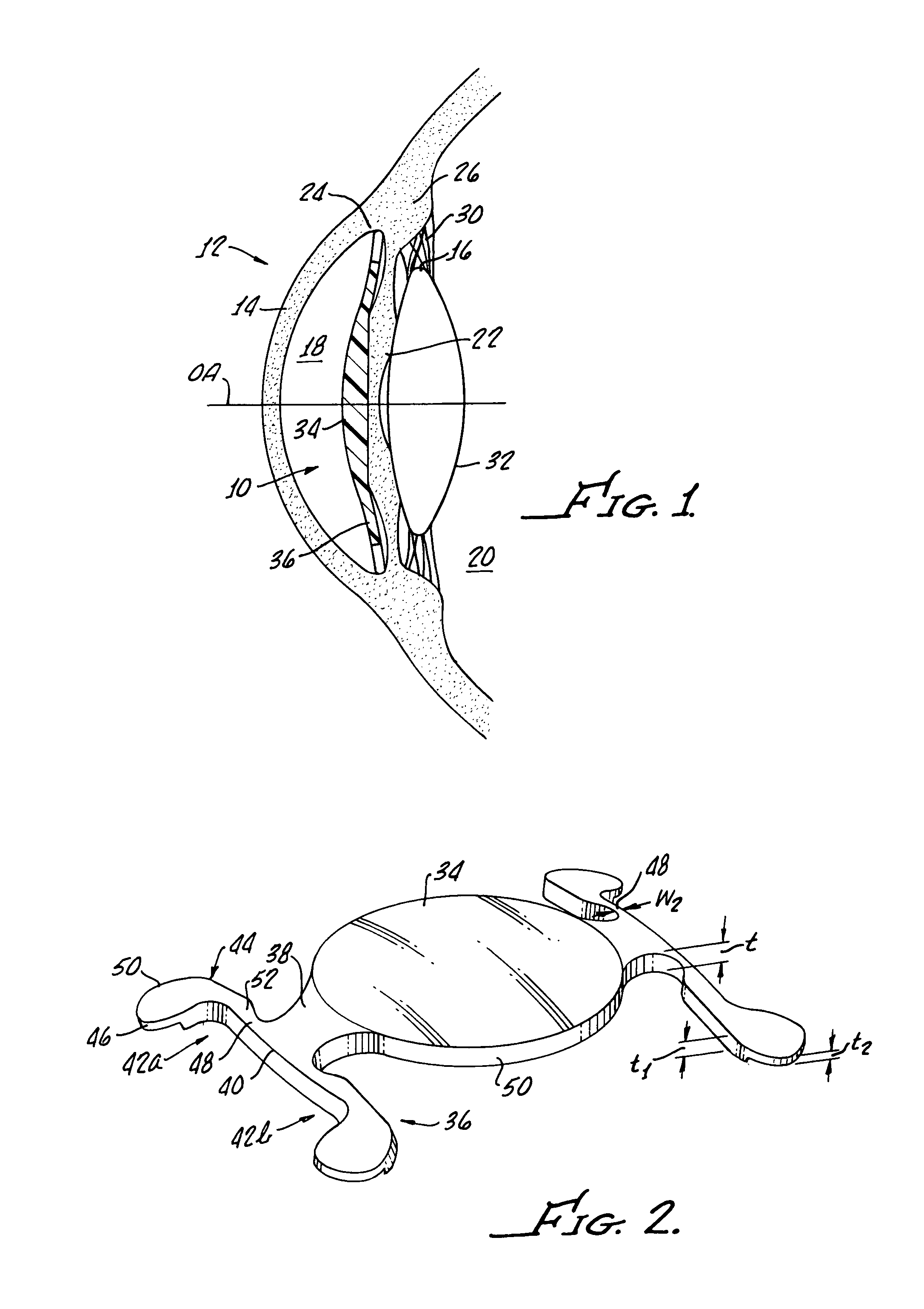
[0032]Referring now to FIG. 1, an anterior chamber IOL (IOL) 10 of the present invention is shown implanted in an eye 12. The eye 12 comprises a cornea 14 shown to the left or front of the eye and an annular iris 16 shown in the middle of the eye. The iris 16 divides the eye 12 into an anterior chamber 18 at the front of the eye and a posterior chamber 20 in back of the iris. The iris 16 also defines the aperture or pupil 22, which is a variable opening in the middle of the iris. The posterior face of the cornea 14 and the anterior face of the iris 16 meet at the scleral spur defining an iridiocorneal angle 24. Behind the iris 16 is the ciliary process 26, which controls the movements of the natural crystalline lens 32 of the eye 12 via a plurality of fibrous zonules 30.

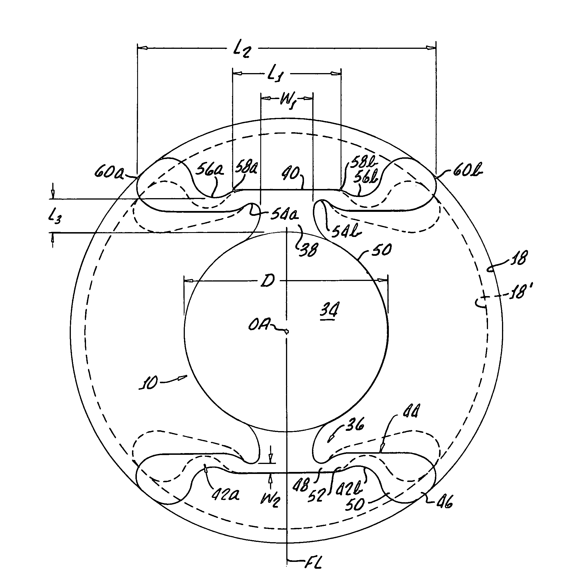
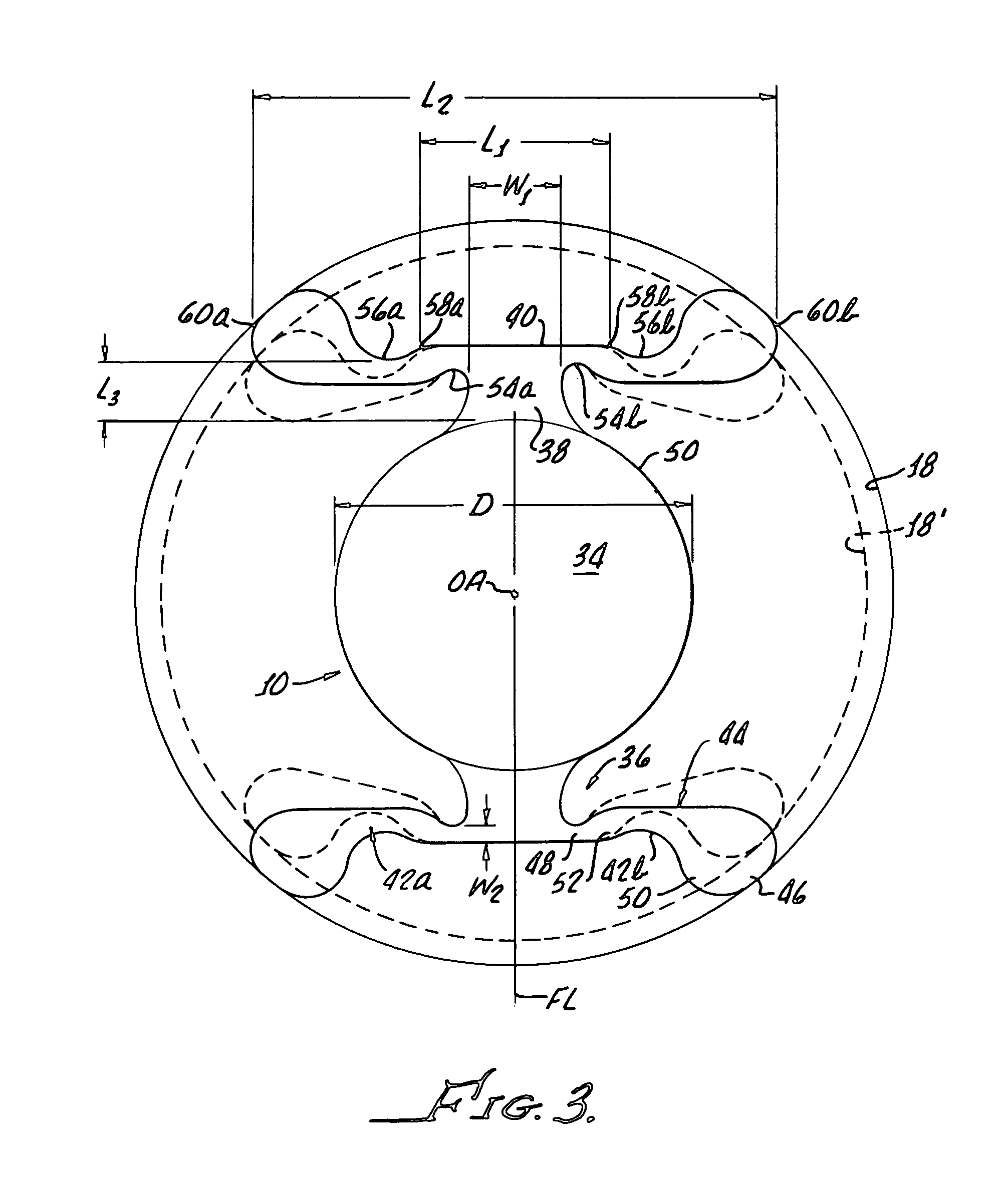
[0033]Still referring to FIG. 1, with additional reference to FIGS. 2 and 3, the anterior chamber IOL 10 of the present invention comprises an optic 34 that is supported in front of the pupil 22 by fixation members 3...


PUM


Abstract

A foldable intraocular lens (IOL) includes an optic and at least one fixation member for supporting the optic in the anterior chamber of an eye. The fixation member includes an intermediate portion that extends a first direction away from the optic, and a leg portion that intersects with an outer end of the intermediate portion and extends a second direction, different from the first direction, away from the outer end. The leg portion preferably includes a reduced width region near the intersection with the intermediate portion. The reduced width region acts essentially as a hinge allowing the leg portion to flex about the intermediate portion in responsive to compressive forces, while the intermediate portion and optic remain stable.

Description

[0001]This invention relates to intraocular lenses (IOLs). More particularly, the invention relates to IOLs placed in the anterior chambers of eyes which provide at least one benefit, for example, at least one of the following benefits: a reduction in the incidence of one or more complications in the eye caused by prior anterior chamber IOLs; effective foldability for safe and controlled insertion in the eye through a small incision; reduced IOL retention forces and a reduction in the tendency of the optics of the IOLs to vault due to a desirable compressive bias of the IOL when fit within the eye.[0002]The human eye is susceptible to numerous disorders and diseases, a number of which attack the crystalline lens. For example, cataracts mar vision through cloudy or opaque discoloration of the lens of the eye, and can result in partial or complete blindness. When this happens, the crystalline lens can be removed and replaced with an intraocular lens, or IOL. In certain other circumsta...

Claims


Application Information

Patent Timeline
Patent Type & Authority Patents(United States)
IPC IPC(8): A61F2/16
CPCA61F2/1613Y10S623/912A61F2002/1681A61F2250/0018
Inventor BRADY, DANIEL
Owner JOHNSON & JOHNSON SURGICAL VISION INC
Why Eureka
Try Eureka