Survey system

a technology of survey system and automatic collimation, applied in the field of survey system, can solve the problems of inability to smoothly perform survey and consume a lot of time for automatic collimation, and achieve the effect of reducing the time required for automatic collimation, and reducing the burden on the operator

Active Publication Date: 2007-12-04
KK TOPCON
View PDF6 Cites 59 Cited by
  • Summary
  • Abstract
  • Description
  • Claims
  • Application Information

AI Technical Summary

Benefits of technology

[0034]According to the invention of Claim 1, the rotation command means or the rotation means determines a rotational direction of the body of the surveying instrument based on an angular difference between a direction angle obtained when the target is caused to substantially exactly face the surveying instrument at the last measurement and a direction angle obtained when the target is caused to substantially exactly face the surveying instrument at the present measurement. Therefore, the instrument body can automatically determine a rotational direction appropriate for catching guide light emitted from the target by a minimum rotation angle without imposing a burden on an operator, and the time required for automatic collimation can be shortened as much as possible without increasing a burden imposed on the operator, thus making it possible to improve working efficiency.
[0035]According to the invention of Claim 2, the rotation command means or the rotation means determines the rotation angle of the body of the surveying instrument to be the angular difference. Therefore, a case never occurs in which the surveying instrument fails to catch guide light emitted from the target because of the influence of, for example, noise, so that the instrument body is excessively rotated, and hence the time taken until the guide light emitted from the target is caught is prevented from becoming long.
[0036]According to the invention of Claim 3, the rotation command means or the rotation means rotates the body of the surveying instrument in a rotational direction determined based on the angular difference if the angular difference is greater than a maximum estimated error angle of the azimuth angle sensor, and the rotation command means or the rotation means determines an excessive angle that is greater by the maximum estimated error angle than the angular difference, then rotates the body of the surveying instrument by the excessive angle, and reverses the body of the surveying instrument if the angular difference of the direction angle is smaller than the maximum estimated error angle. Therefore, the guide light emitted from the target can be caught by rotating the instrument body by an appropriate rotational pattern in accordance with the angular difference, and automatic collimation can be reliably performed in a shorter time.
[0037]According to the invention of Claim 4, if an angular difference of the direction angle is greater than the sum of the maximum estimated error angle of the azimuth angle sensor and a safe error angle obtained by affording a margin for the error angle, the rotation command means or the rotation means rotates the body of the surveying instrument in a rotational direction determined based on the angular difference, and, if the angular difference of the direction angle is greater than the maximum estimated error angle and is smaller than the sum of the maximum estimated error angle and the safe error angle, the rotation command means or the rotation means determines an excessive angle greater by the sum of the maximum estimated error angle and the safe error angle than the angular difference, then rotates the body of the surveying instrument by the excessive angle, and reverses the body of the surveying instrument, and, if the angular difference of the direction angle is smaller than the maximum estimated error angle, the rotation command means or the rotation means determines an excessive angle greater by the maximum estimated error angle than the angular difference and a return angle equal to the sum of twice the maximum estimated error angle and the safe error angle, then rotates the body of the surveying instrument by the excessive angle, then reverses the body of the surveying instrument by the return angle, and again rotates the body of the surveying instrument in the direction determined first. Therefore, the guide light emitted from the target can be caught by rotating the instrument body by an appropriate rotational pattern in accordance with the angular difference, and automatic collimation can be reliably performed in a shorter time.
[0038]According to the invention of Claim 5, the azimuth angle sensor is a magnetic sensor. Therefore, the present invention can be easily realized at low cost.[

Problems solved by technology

However, a conventional problem resides in the fact that, when the surveying instrument having the automatic collimator or the surveying instrument having the remote control device performs a survey in accordance with a command emitted from the remote control device, the telescope must scan a wide range in order to set the target within a narrow visual field of the telescope, and hence much time is consumed for automatic collimation, and the survey cannot be smoothly performed.

Method used


Image

  • Survey system
  • Survey system
  • Survey system

Examples


first embodiment

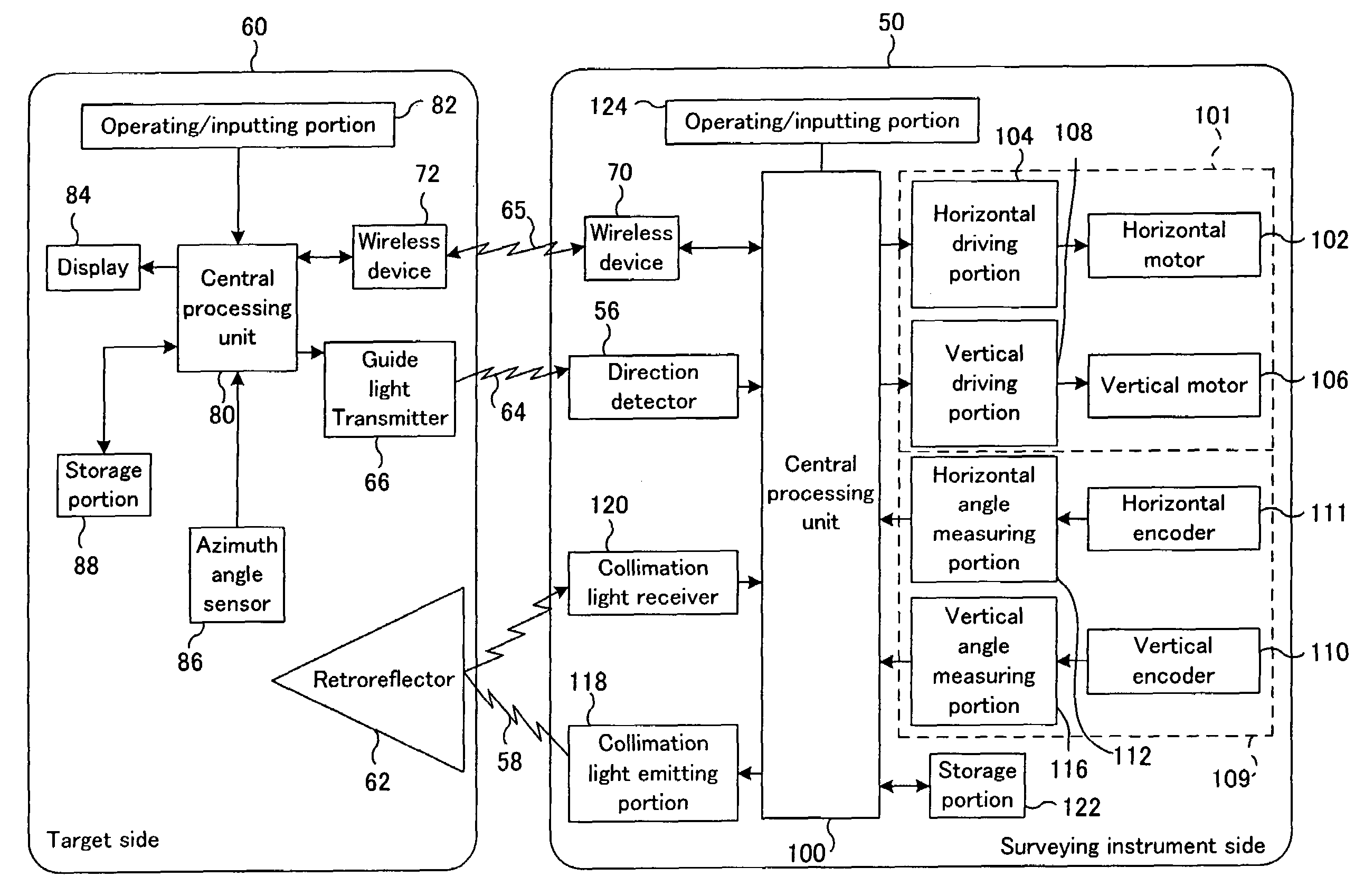
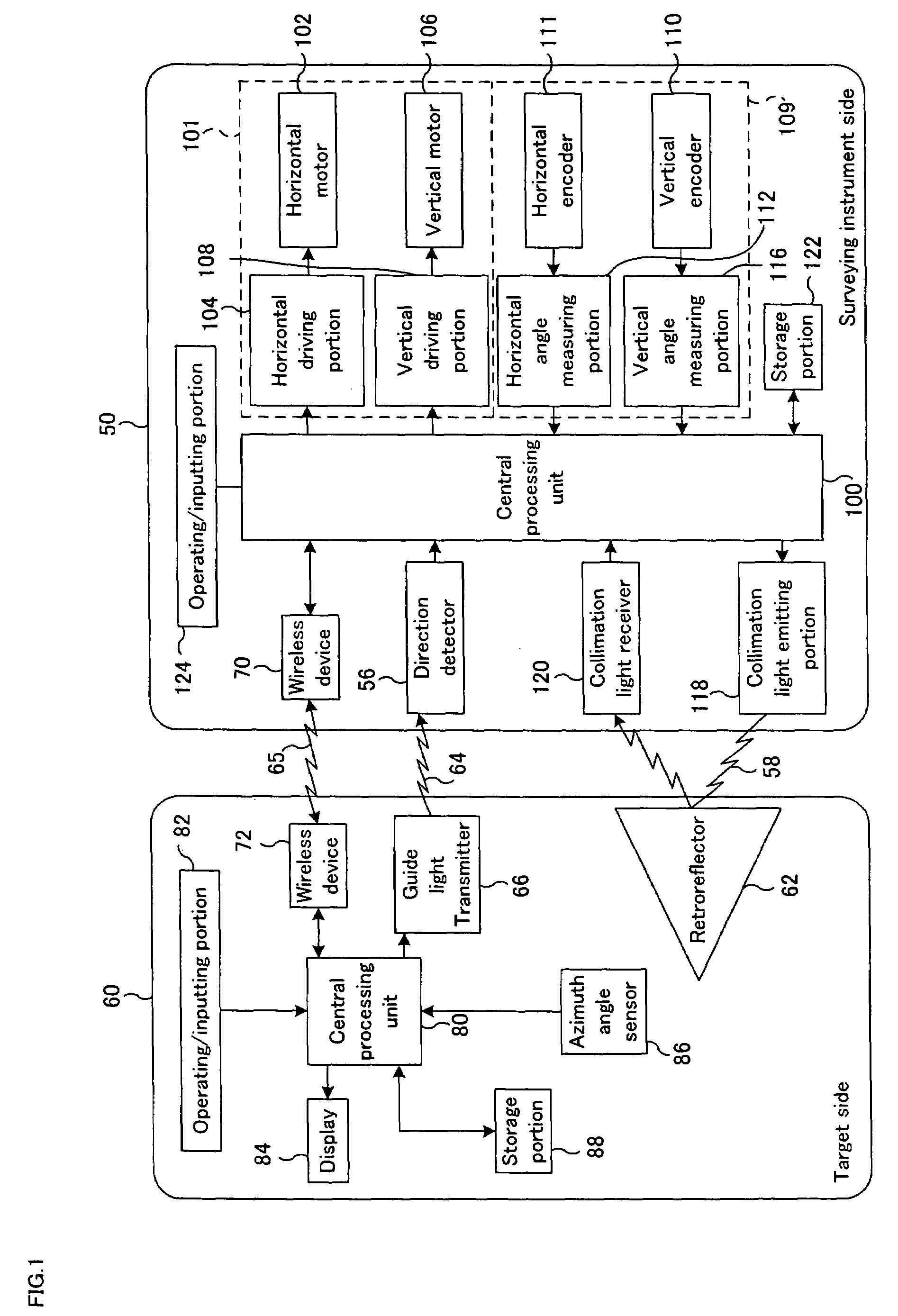
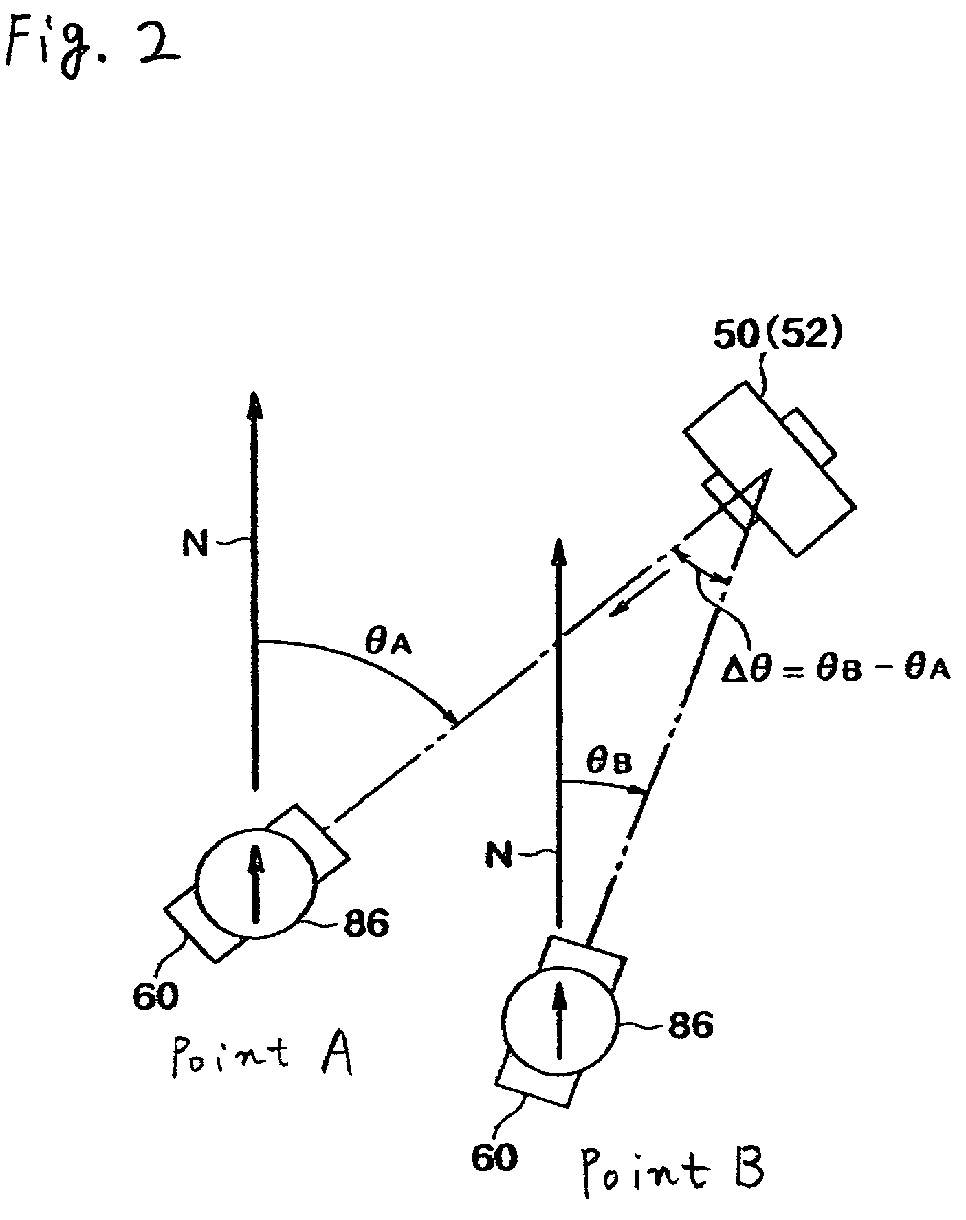
[0040]First, the present invention will be described with reference to FIG. 1 to FIG. 3. FIG. 1 is a block diagram of the whole of a survey system according to this embodiment. FIG. 2 is a view for explaining the principle of the present invention. FIG. 3 is a flowchart explaining a process for adjusting the body of a surveying instrument approximately toward a target in this survey system.

[0041]As shown in FIG. 1, the survey system has a target 60 including a guide light transmitter 66, an azimuth angle sensor 86 that measures the direction of the target 60, and a storage portion 88 that stores a direction angle (azimuth angle) measured by the azimuth angle sensor 86. A central processing unit (CPU) 80 is connected to the azimuth angle sensor 86 and the storage portion 88. The central processing unit (CPU) 80 causes the azimuth angle sensor 86 to measure a direction angle and causes the storage portion 88 to store this direction angle every time the distance and angle are measured ...

second embodiment

[0059]In the flowchart of FIG. 7, an angular difference Δθ between the direction angle θB obtained at the present time and the direction angle θA obtained at the last time is calculated at step S25 in the same way as in the second embodiment shown in FIG. 4. However, in this embodiment, the process then proceeds to step S40, at which a comparison is made among the angular difference Δθ, the maximum estimated error angle E and the safe error angle E′.

[0060]If E+E′41, at which the rotational direction of the instrument body 52 is determined in the same way as in the first embodiment, and a rotation command of a rotational pattern P1 by which the instrument body 52 is simply rotated in an indicated rotational direction is formed (see FIG. 6(A)).

[0061]If E42, at which the excessive angle θ1 is determined as θ1=Δθ+E+E′, and a rotation command of a return-type rotational pattern P2, by which the instrument body 52 is rotated by the excessive angle θ1, and continues to be reversed (see FIG...

third embodiment

[0076]FIG. 6 View for explaining a rotational pattern by which the instrument body is rotated in the survey system according to the present invention.

[0077]FIG. 7 Flowchart explaining a process for positionally adjusting the instrument body approximately toward the target in the survey system according to the third embodiment.

[0078]FIG. 8 View showing the outline of the conventional survey system.

[0079]FIG. 9 Block diagram of the whole of the conventional survey system.

[0080]FIG. 10 Flowchart explaining the measuring process of the conventional survey system.


PUM


Abstract

A survey system is made up of a target and a surveying instrument provided with an automatic collimator that automatically collimates the target. The target includes a guide light transmitter that emits guide light, an azimuth angle sensor that detects a direction angle (θA, θB) at which the target is directed, and a central processing unit that sends a rotation command, which includes the rotational direction of the instrument body, to the surveying instrument. The central processing unit determines the rotational direction of the instrument body based on an angular difference (θB-θA) between a direction angle (θA) obtained when the target is caused to approximately face the surveying instrument at the last measurement and a direction angle (θB) obtained when the target is caused to approximately face the surveying instrument at the present measurement.

Description

TECHNICAL FIELD[0001]The present invention relates to a survey system that can remotely control a surveying instrument from a target side by a single operator.BACKGROUND ART[0002]In order to measure the position of a survey point or the like by using a conventional surveying instrument such as a total station (electric distance / angle meter), it was necessary to collimate a target placed at the survey point. In recent years, a surveying instrument having an automatic collimator has appeared on the market in order to reduce labor required to collimate a target and in order to reduce collimation errors committed by an operator. An automatic collimator is a device for determining the direction of a target by emitting a beam of collimation light along the collimation axis (optical axis) of a telescope of the surveying instrument and by receiving the collimation light reflected from the target so as to automatically and accurately direct the telescope toward the target. The surveying inst...

Claims


Application Information

Patent Timeline
Patent Type & Authority Patents(United States)
IPC IPC(8): G01B11/26
CPCG01C1/00G01C15/002G01C15/00G01C1/02
Inventor YASUTOMI, SATOSHICHIBA, MINORUNISHITA, NOBUYUKI
Owner KK TOPCON
Why Eureka
Try Eureka