Power supply

a power supply and capacitor technology, applied in the direction of emergency protective arrangements, switch power arrangements, contact mechanisms, etc., can solve the problems of increasing difficulty in designing an impedance-coupling power supply, power transfer is not optimized, and constant load power, etc., to achieve low impedance, good power delivery to load, and high value coupling impedance

Inactive Publication Date: 2007-12-04
FIELDMETRICS
View PDF13 Cites 38 Cited by
  • Summary
  • Abstract
  • Description
  • Claims
  • Application Information

AI Technical Summary

Benefits of technology

[0023]One advantage of the present invention is that a high value coupling impedance can be used with a low impedance load and still achieve good power delivery to the load.
[0024]Another advantage of the present invention is that it is lightweight compared with other solutions.
[0025]Another advantage of the present invention is that the transformer and the coupling impedance have a resonant frequency that is far lower than the operating frequency, rather than selected to resonate at the operating frequency, as in a CCVT.
[0026]Another advantage of the present invention is that it is very compact in size.
[0027]Another advantage of the present invention is that it is capable of withstanding lightning impulse, switching surge and continuous AC over-voltages that are required of any equipment to be installed in a power utility system.
[0028]Another advantage of the present invention is that very high power supply efficiency can be achieved without using a switching regulator.

Problems solved by technology

This approach has difficulties in providing a constant load power when significant variations in the line current occur.
The power supply is functional, but the power transfer is not optimized, since the impedance of the power supply is approximately 2.65 kohms, more than ten times higher than the load impedance.
The ability to design an impedance-coupling power supply becomes increasingly difficult with larger differences in voltage between the AC voltage source and the DC voltage at the load.
For example, it is difficult to achieve a coupling capacitance of more than 1 nF in a lightweight package when voltage sources of >10,000 VAC are considered.
For a 10,000 VAC voltage source and a load impedance of 200 ohms, providing 10 VDC across the load requires a coupling capacitor of about 13 nF, which is difficult to achieve in a compact, low weight package.
The use of polarized capacitors as disclosed by Cambier et al. is not possible at higher source voltages because of the difficulty in providing rectifier diodes with the required voltage withstand capability.

Method used


Image

  • Power supply
  • Power supply
  • Power supply

Examples


Embodiment Construction

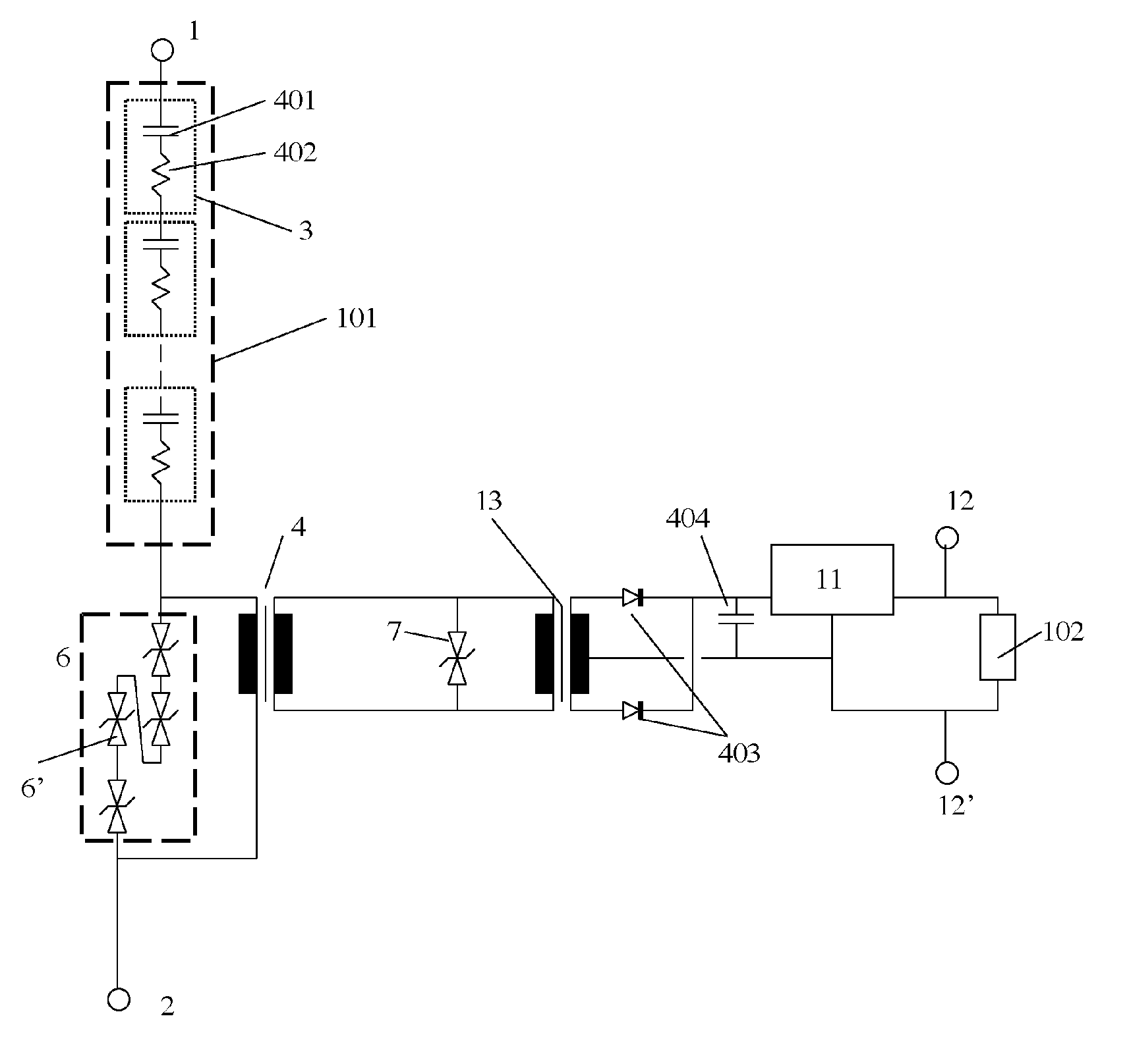
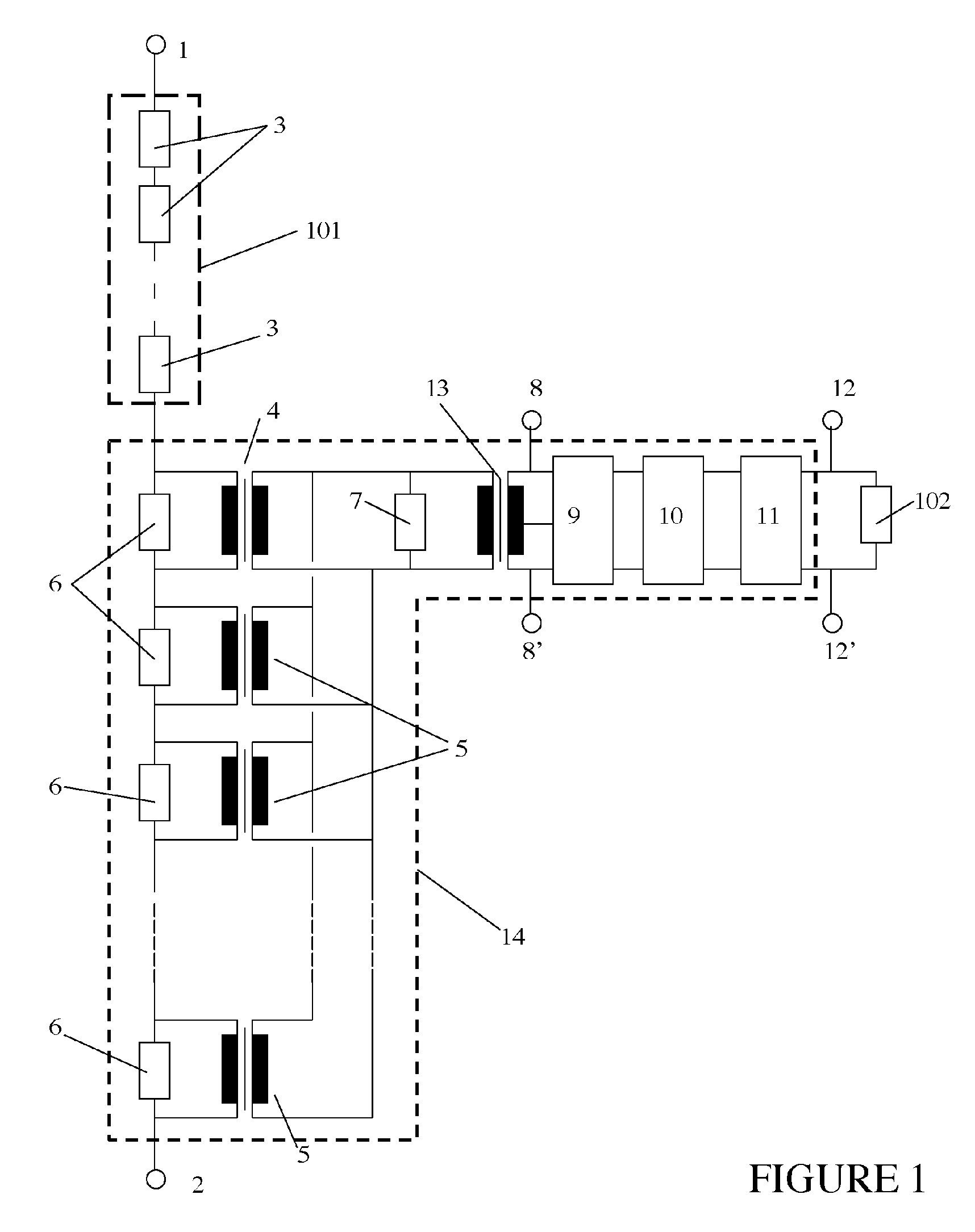
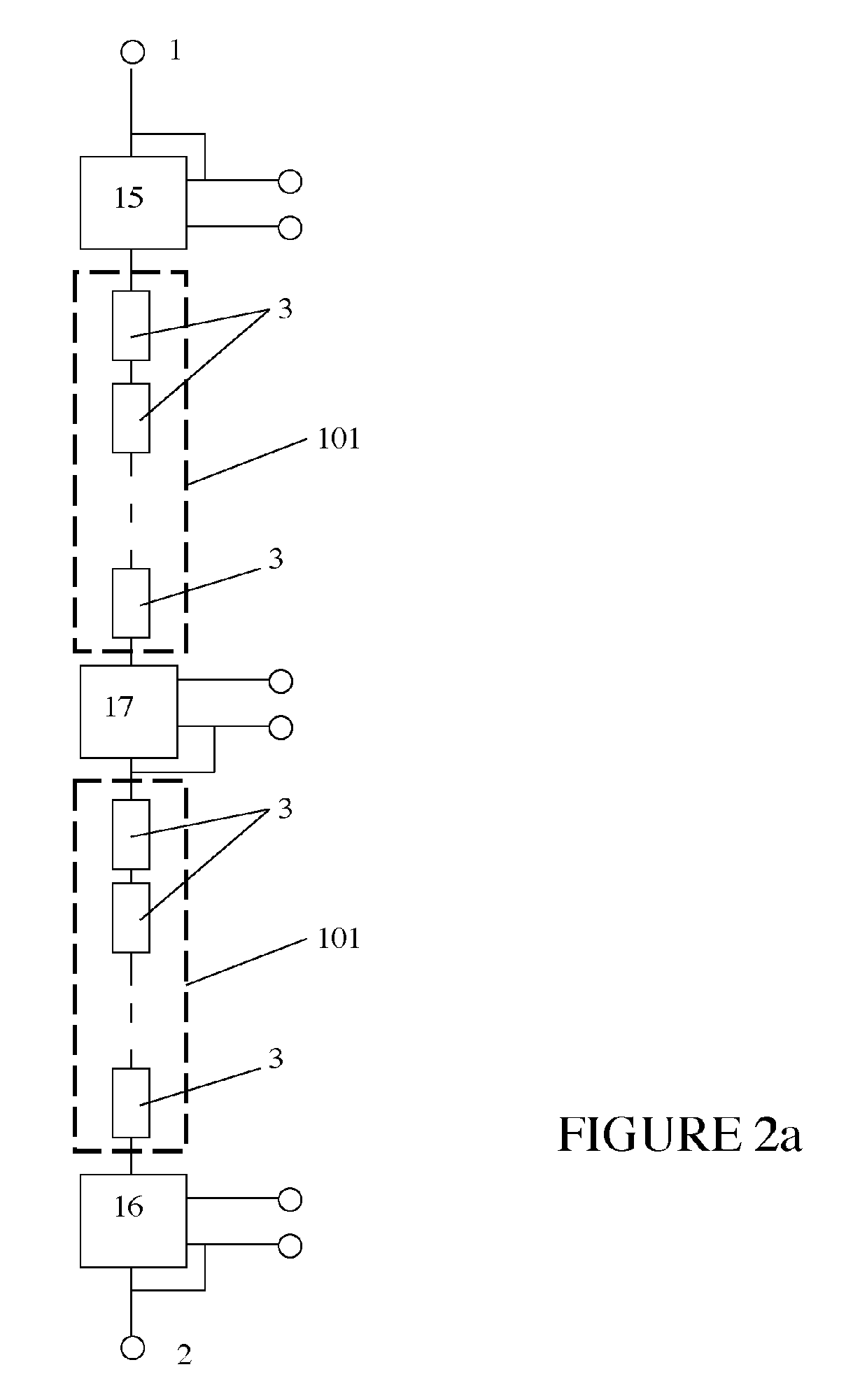
[0036]FIG. 1 shows a schematic diagram of the power supply. The device is connected between two conductors 1 and 2 that establish an AC voltage difference across the device. The conductor 1 or 2 can be one phase of a three-phase power line, a common neutral connection, or a ground connection. One of the conductors is connected to a high voltage string 101 comprised of electrical impedance elements 3 that are connected in series. The impedance elements 3 are selected from the list including but not limited to a capacitor, a resistor, a capacitor in series with a resistor, a capacitor in parallel with a resistor, or a capacitor in parallel with a resistor that is in series with a resistor, although the preferred embodiment is a polymer film / foil capacitor in series with a wire-wound resistor. The opposite end of the high voltage string 3 is connected to one side of the primary of a transformer 4. At least one or more additional transformers 5 are connected in series with the primary o...


PUM


Abstract

A modular, low weight impedance dropping power supply with battery backup is disclosed that can be connected to a high voltage AC source and provide electrical power at a lower voltage. The design can be scaled over a wide range of input voltages and over a wide range of output voltages and delivered power.

Description

CROSS REFERENCE TO PRIOR APPLICATION[0001]This application claims the priority of U.S. Provisional Application Ser. No. 60 / 522,394 filed Sep. 24, 2004 and entitled “POWER SUPPLY”, the subject matter of which is incorporated herein by reference.FEDERAL GOVERNMENT STATEMENT[0002]This invention was made with Government support under contract DE-FG03-01ER83228 awarded by the Department of Energy. The Government has certain rights to this invention.FIELD OF THE INVENTION[0003]The present invention relates to an impedance or capacitor dropping power supply to provide power for equipment located on or near a high voltage power transmission line.DESCRIPTION OF THE PRIOR ART[0004]In alternating-current (AC) power systems, it is often desired to provide electrical power for equipment that is connected to a high voltage power line or bus conductor. Normally this is achieved using a step-down transformer to convert the high voltage between the power line and ground into a lower voltage that is ...

Claims


Application Information

Patent Timeline
Patent Type & Authority Patents(United States)
IPC IPC(8): H02M7/06
CPCH02M7/06H02M5/06
Inventor YAKYMYSHYN, CHRISTOPHER PAULHAMILTON, PAMELA JANEBRUBAKER, MICHAEL ALLEN
Owner FIELDMETRICS
Why Eureka
Try Eureka