
Method for ordering and transmitting of digital data amounts, particularly video signal

a digital data amount and video signal technology, applied in the field of video signals, can solve the problems of high cost, limited capacity of terrestrial all-purpose transmission channels used for internet, and inability to transmit quality video signals, etc., and achieve the effect of reducing costs and high capacity

Inactive Publication Date: 2007-12-04
IP VISION
View PDF6 Cites 0 Cited by
  • Summary
  • Abstract
  • Description
  • Claims
  • Application Information

AI Technical Summary

Benefits of technology

This method achieves sufficient transmission capacity at lower costs than traditional satellite links and internet methods, reducing satellite usage to 10-20% of overall time, enabling efficient real-time video delivery to single or multiple receivers while maintaining data integrity.

Problems solved by technology

Present terrestrial all-purpose transmission channels used for internet have restricted capacity.
This means that internet is not suitable for transmission of quality-videosignal, that is to say a video program in real-time.
An alternative is satellite transmission, but this has been too expensive for single real-time transmission of data packets to private users until now.
The development of broadband networks with high capacity has not yet reached to the extent that there is a world covering net.
Nevertheless this signal architecture is not used to increase the transmission rate up to a real-time transmission.

Method used


Image

  • Method for ordering and transmitting of digital data amounts, particularly video signal
  • Method for ordering and transmitting of digital data amounts, particularly video signal
  • Method for ordering and transmitting of digital data amounts, particularly video signal

Examples


Embodiment Construction

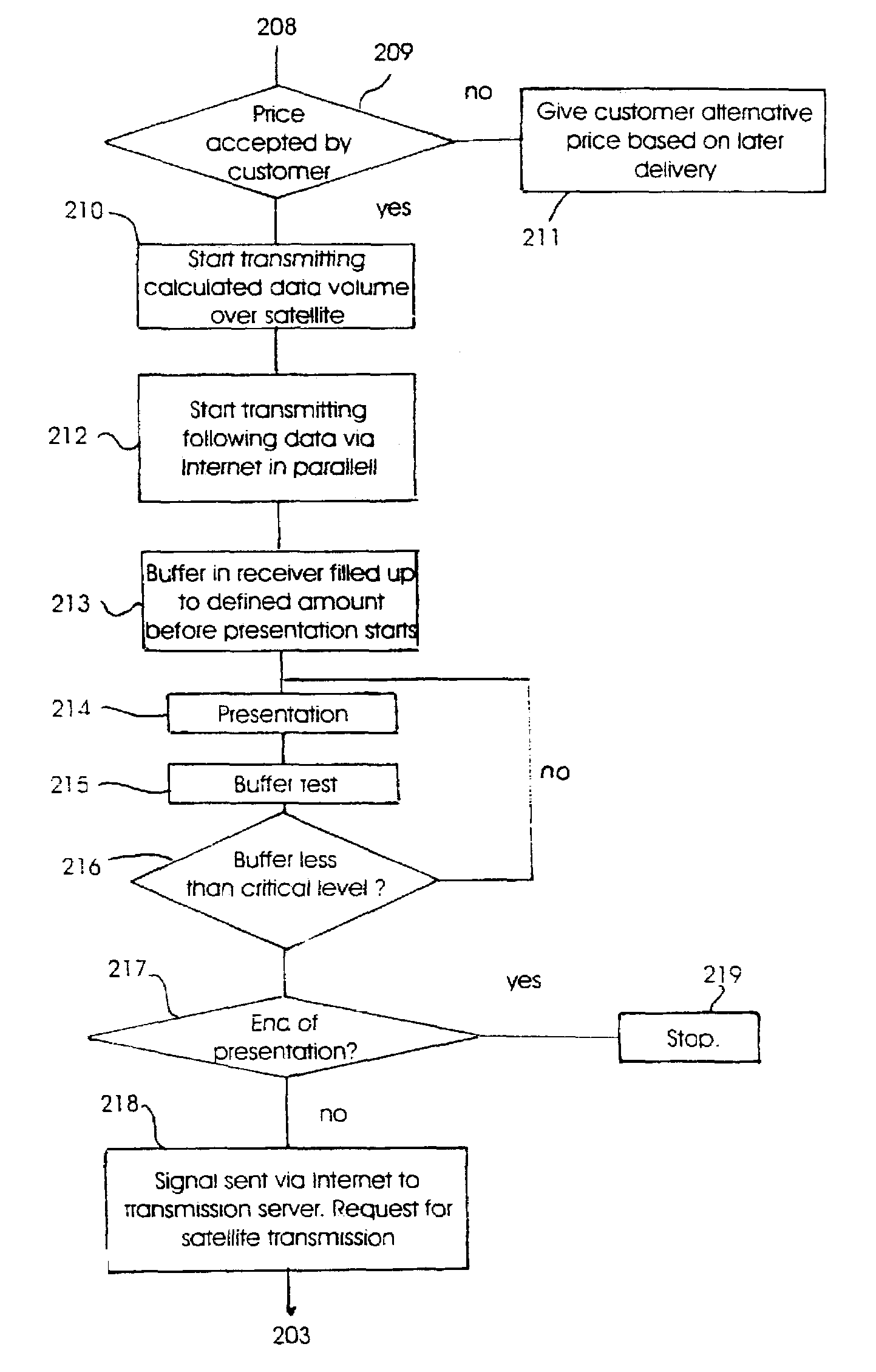
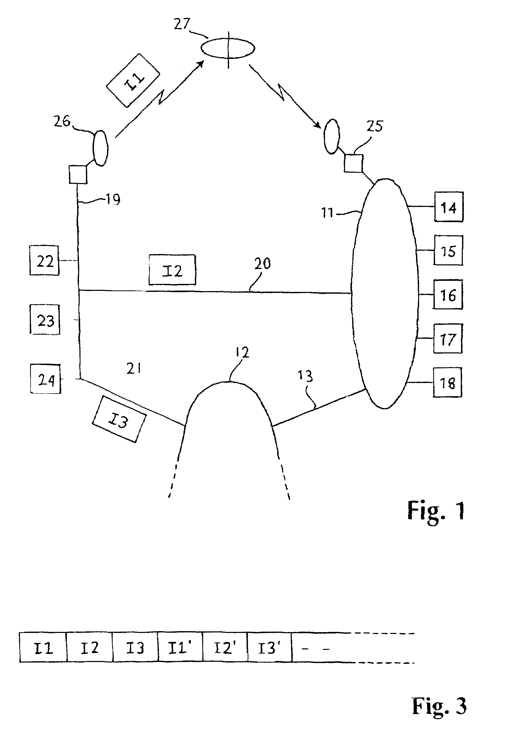
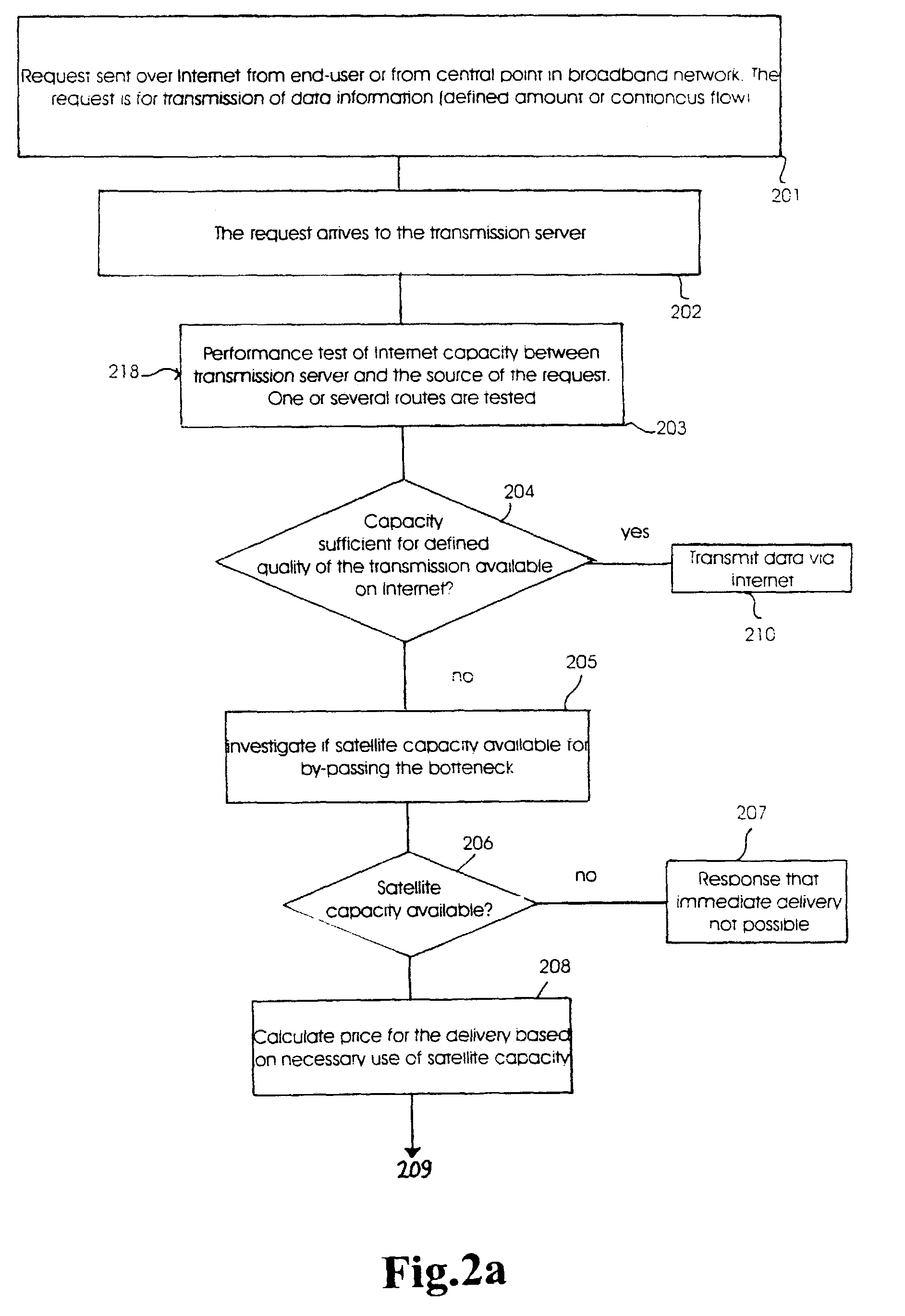
[0025]Referring to FIG. 1, two broadband networks 11 and 12 are connected with a narrowband internet line 13. The network 11 is shown with a number of receivers connected with users or subscribers which are marked with reference numbers 14-18. The receivers 14-18 can be data machines which are connected to the broadband network 11 by modem or another receiving unit with suitable data power, which is able to communicate with the broadband network correspondingly. The receivers 14-18 practically will be receivers of data files, which can search, find and download these files from an arbitrary place in an extensive network. Practically this means internet or “world wide web”.

[0026]The two broadband networks 11 and 12 are also connected with a further broadband network 19 over respective internet lines 20 and 21. Connected to the third broadband network 19 are a number of data suppliers or transmitters 22-24. Each of the two broadband networks 11 and 19 are also connected tpo satellite ...


PUM


Abstract

Method for ordering and transmission of digital data, particularly video signals, from a transmitter to a single receiver or a group of receivers where other transmission channels are searched for finding a reasonable alternative. A data signal is sent with a request for transmission of a determined video signal from a receiver to a transmitter. A data packet (I1), being a first part of the signal, is transmitted from the transmitter over a satellite channel. A following part of the signal is transmitted as another data packet (I2) over a narrowband communication channel, such as a low-cost Internet channel. Supervision of the received non-used data amount is carried out in a buffer storage at the receiver. By registering non-used data (buffer amount) at the receiver below a certain level a warning signal will be sent from the receiver to the transmitter. When receiving this warning signal the transmitter initiated transmission to the receiver of a further data packet (I1′) of the signal over the satellite channel, for thereafter continuing with transmission of a further signal amount (I2′) over the narrowband channel. This alternating transmission will be continued to save transmission capacity over the satellite connection and at the same time to maintain a transmission capacity which results in a satisfying data content in the transmitted signal.

Description

[0001]This application is a filing under 35 USC 371 of PCT / NO01 / 00122 filed Mar. 22, 2001.[0002]Method for ordering and transmission of digital data, particularly video signals, from a transmitter to a single receiver or a group of receivers.BACKGROUND OF THE INVENTION[0003]Present terrestrial all-purpose transmission channels used for internet have restricted capacity. At high traffic levels the capacity can approach zero. With today's compression techniques a video signal will ideally require more than 1,5 Mb / s, or at least 500 Kb / s. This means that internet is not suitable for transmission of quality-videosignal, that is to say a video program in real-time.[0004]An alternative is satellite transmission, but this has been too expensive for single real-time transmission of data packets to private users until now. The development of broadband networks with high capacity has not yet reached to the extent that there is a world covering net.[0005]Transmission protocols are known wherei...

Claims


Application Information

Patent Timeline
Patent Type & Authority Patents(United States)
IPC IPC(8): G08C15/00H04J3/16H04J3/22H04L12/28H04L12/56H04L12/54H04L29/06H04N7/173H04N7/24
CPCH04L12/5692H04N7/17309H04N21/6377H04N21/6402H04L69/165H04N21/64738H04N21/658H04L69/16H04L69/166H04N21/6405
Inventor BERGSTROM, ROGER
Owner IP VISION
Learn More