System and method for drawing and manufacturing bent pipes

a technology of bent pipes and manufacturing methods, applied in static indicating devices, instruments, electric/magnetic computing, etc., can solve the problems of not being able to spend the resources necessary to offer custom objects in plug-in applications, complicated cad programs, and limited standard objects

Active Publication Date: 2007-12-04
GCC
View PDF9 Cites 11 Cited by
  • Summary
  • Abstract
  • Description
  • Claims
  • Application Information

AI Technical Summary

Benefits of technology

[0021]A particular data structure further includes a fourth field containing data representing the length of a first line segment, a fifth field containing data representing the length of a second line segment, and a sixth field containing data representing an angle between the first line

Problems solved by technology

While some CAD programs appear quite complex, and offer the designer a great variety of drawing tools, such programs are essentially only drawing engines.
Known plug-in applications are limited to standard objects that are used repeatedly in systems being designed.
It is not,

Method used


Image

  • System and method for drawing and manufacturing bent pipes
  • System and method for drawing and manufacturing bent pipes
  • System and method for drawing and manufacturing bent pipes

Examples


Embodiment Construction

[0033]The present invention overcomes the problems associated with the prior art, by providing a system and method for entering a custom bent-tube object in a drawing file, and for using said bent-tube object to generate bender driver data. In the following description, numerous specific details are set forth (e.g., drawing engine, bender machine type, etc.) in order to provide a thorough understanding of the invention. Those skilled in the art will recognize, however, that the invention may be practiced apart from these specific details. In other instances, details of well known CAD system and manufacturing practices and components have been omitted, so as not to unnecessarily obscure the present invention.

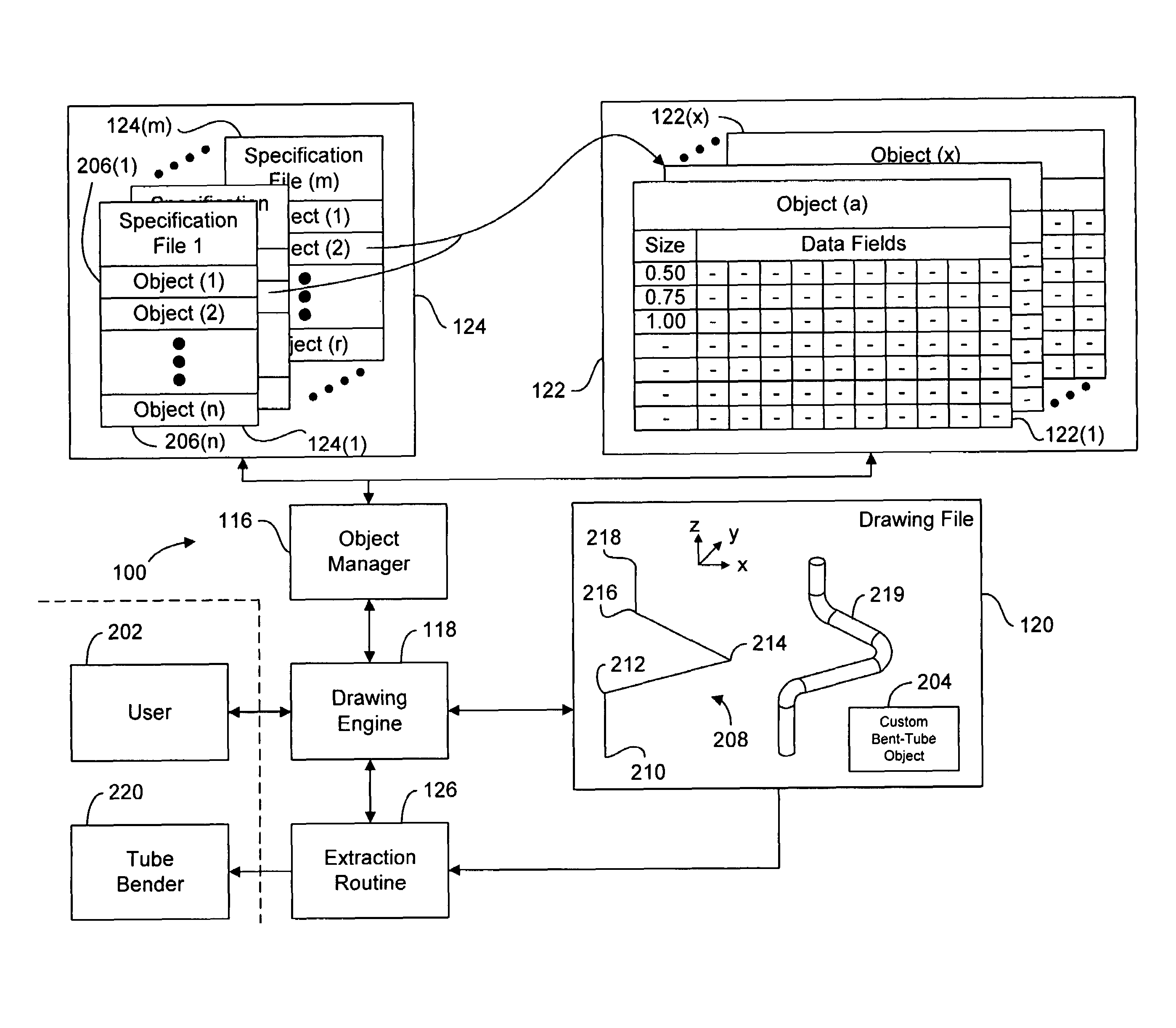
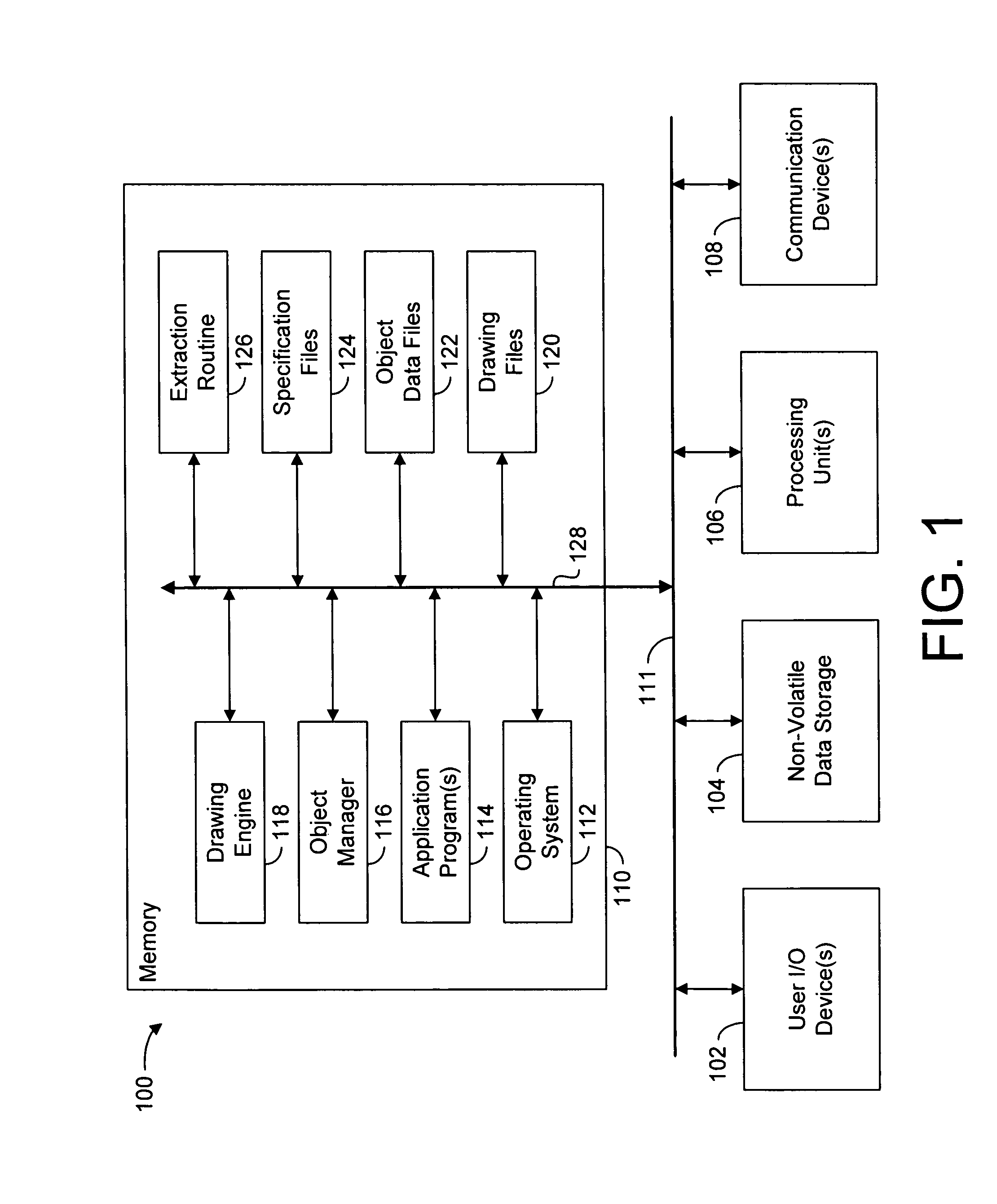
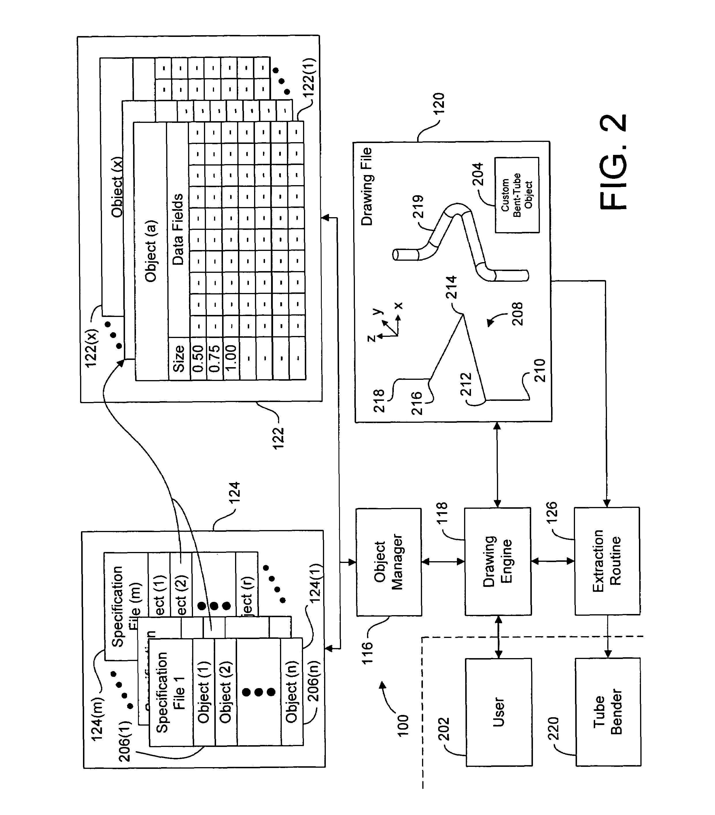
[0034]FIG. 1 is a block diagram of a design system 100 according to one embodiment of the present invention. System 100 includes user I / O devices 102, nonvolatile memory 104, processing unit(s) 106, communication devices 108, and working memory 110, all intercommunicating via int...


PUM


Abstract

Novel systems and methods of using a bent-tube object in a drawing file include entering a custom bent-tube object in a drawing file, and using the bent tube object to generate bender driver data. In a particular method, the step of entering the custom bent-tube object in the drawing file includes entering a multi-segmented line, and generating the custom bent-tube object based at least in part on the lengths of and angles between the segments of the multi-segmented line. In a more particular method, the step of entering the custom bent-tube object further includes selecting a tube type (e.g., a particular diameter, material, etc.), and the step of generating the custom bent-tube object further includes retrieving bent-tube object data from an object data file based at least in part on the tube type.

Description

RELATED APPLICATIONS[0001]This application is a continuation of U.S. patent application Ser. No. 10 / 072,664 (now issued as U.S. Pat. No. 6,757,576), filed Feb. 5, 2002 by the same inventors, which is incorporated herein by reference in its entirety.BACKGROUND OF THE INVENTION[0002]1. Field of the Invention[0003]This invention relates generally to the design and manufacturing of piping and plumbing systems, and more particularly to a system and method for designing and manufacturing systems including bent tubing. Even more particularly the present invention relates to a system and method for entering a bent-tube object in a CAD drawing file, and for using the bent-tube object to generate data for driving a tube bender to manufacture a bent tube.[0004]2. Description of the Background Art[0005]Computer assisted design (CAD) systems are well known and widely used in the design of mechanical devices, architectural structures, landscaping, and the like. Known systems (e.g., AutoCAD) allow...

Claims


Application Information

Patent Timeline
IPC IPC(8): G06F19/00G06FG06F17/50G09G5/00
CPCG06F17/50Y10S715/964G06F2217/34G06F2113/14G06F30/00
Inventor GREER, GARY L.MACK, JOHN D.
Owner GCC
Why Eureka
Try Eureka