Self-propelled working machine

a working machine and self-propelled technology, applied in the direction of agricultural machines, electric control, instruments, etc., can solve the problems of tiresome operation of stopping the engine 205 every time the work is interrupted, and the idling state is unusable, so as to save fuel, reduce the load on the operator, and reduce the effect of engine exhaus

Inactive Publication Date: 2007-12-11
HONDA MOTOR CO LTD
View PDF14 Cites 9 Cited by
  • Summary
  • Abstract
  • Description
  • Claims
  • Application Information

AI Technical Summary

Benefits of technology

[0009]Thus, in this invention, by constructing an engine stopping system using constituent parts which are necessary for the working machine anyway, the engine can be stopped automatically. Also, because it is not necessary for the operator to stop the engine every time work is interrupted, the load on the operator is lightened. And by idling of the engine being eliminated as much as possible, fuel is saved, engine exhaust is kept down and the working environment is improved, and the life of the engine can be extended.

Problems solved by technology

From the point of view of saving fuel, improving the working environment, and extending the life of the engine, it is undesirable for the idling state to continue.
However, the operation of stopping the engine 205 every time working is interrupted is tiresome.

Method used


Image

  • Self-propelled working machine
  • Self-propelled working machine
  • Self-propelled working machine

Examples


Embodiment Construction

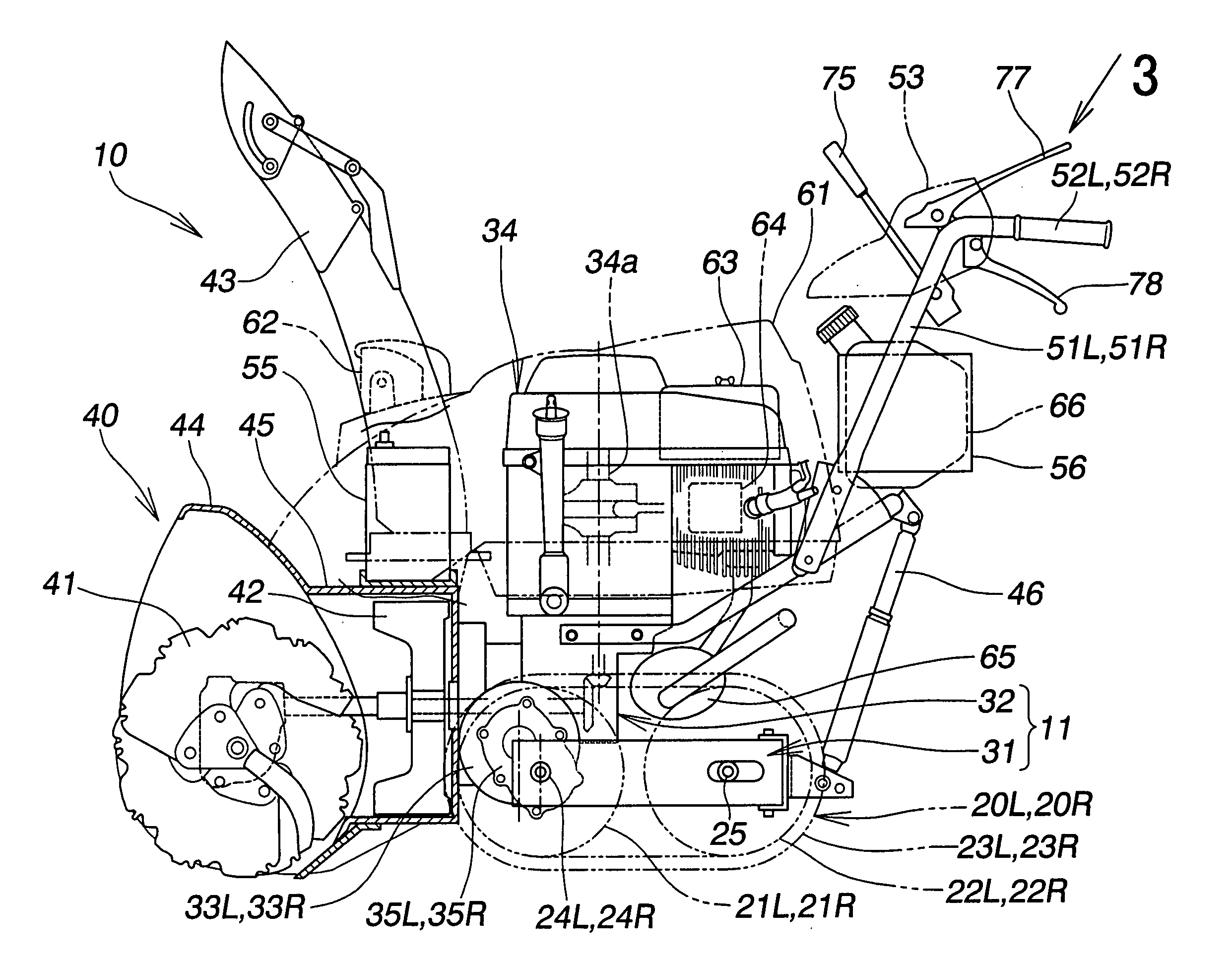
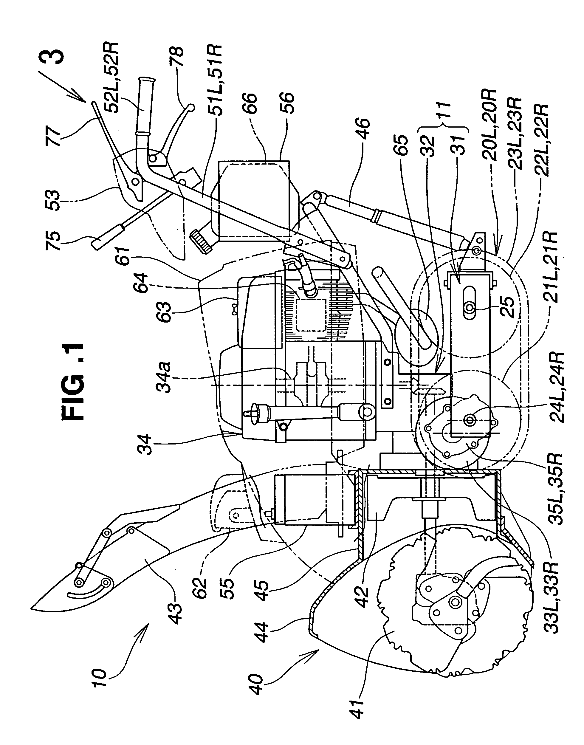
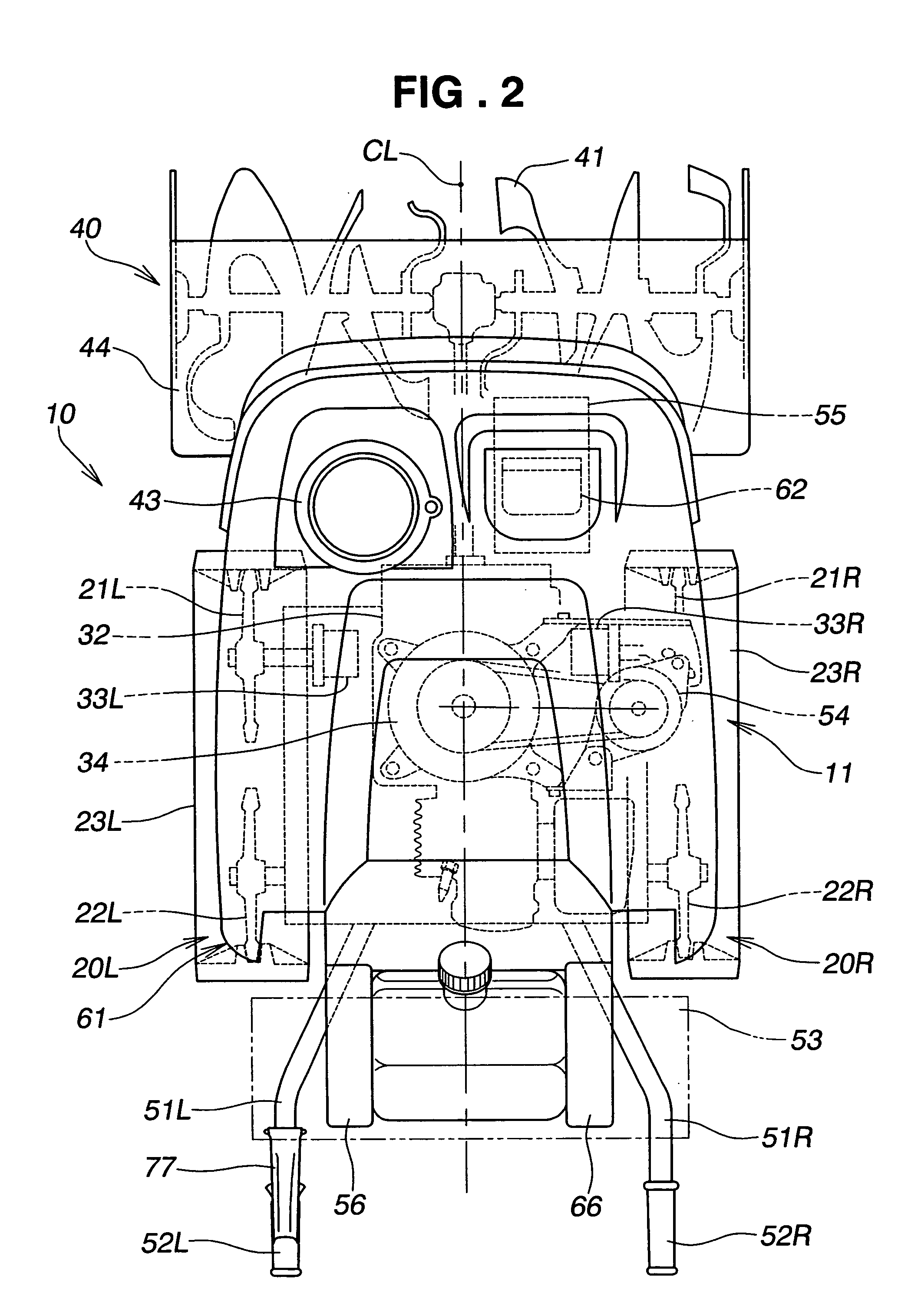
[0022]A preferred embodiment of a working machine will now be described, and as a suitable embodiment of a working machine the example of a snow-remover will be used, as shown in the drawings.

[0023]As shown in FIG. 1 and FIG. 2, a snow-remover 10 includes a machine body 11 made up of a transport frame 31 and a transmission case 32.

[0024]The transport frame 31 has left and right transporting parts 20L, 20R. The transmission case 32 is attached to the transport frame 31 in such a way that it can swing up and down. Left and right electric motors 33L, 33R are mounted on left and right side parts of the transmission case 32. An engine (internal combustion engine) 34 is mounted on the transmission case 32. A snow-removal working part 40 is mounted on the front of the transmission case 32. Left and right operating handles 51L, 51R extend upward and rearward from the top of the transmission case 32. A control panel 53 is provided between the left and right operating handles 51L, 51R.

[0025]T...


PUM


Abstract

A self-propelled working machine has a pair of transporting parts, a working part, an engine for driving at least the working part, and a main switch for turning the engine on and off. A locomotion preparation switch produces a command for moving the transporting parts when turned on and produces a stop command for stopping movement of the transporting parts when turned off. A locomotion speed setting member orders a target locomotion speed of the transporting parts. A work switch switches the working part on and off. A control part stops the engine when a first condition that the main switch is on, a second condition that the locomotion preparation switch is off, a third condition that the transporting parts have stopped moving and the target locomotion speed ordered by the locomotion speed setting member is zero, and a fourth condition that the work switch is off, are satisfied.

Description

FIELD OF THE INVENTION[0001]The present invention relates to a self-propelled working machine having a working part driven by motive power from an engine, and particularly to a working machine in which under predetermined conditions the engine is automatically stopped.BACKGROUND OF THE INVENTION[0002]As a common working machine, a self-propelled snow remover having a snow-removing part as a working part is disclosed for example in JP-A-2000-80621 and JP-A-2001-271317.[0003]A working machine consisting of the snow-remover disclosed in JP-A-2001-271317 will now be described briefly on the basis of FIG. 8 hereof.[0004]Referring to FIG. 8, a working machine 200 has on a machine body 201 a working part 204 made up of an auger 202 and a blower 203; an engine 205 for driving the working part 204; left and right transporting parts 206, 206 consisting of crawlers; left and right electric motors 207, 207 for driving these transporting parts 206, 206; a generator 209, driven by the engine 205,...

Claims


Application Information

Patent Timeline
Patent Type & Authority Patents(United States)
IPC IPC(8): E01H5/09E01H5/04F02D17/00F02D29/00F02D29/02F02D41/04
CPCF02D41/042E01H5/04
Inventor WAKITANI, TSUTOMUSHIMIZU, NORIKAZUKAWAKAMI, TOSHIAKI
Owner HONDA MOTOR CO LTD
Why Eureka
Try Eureka