Medico-surgical instruments

a technology of surgical instruments and stents, applied in the field of stents, can solve the problems of not being suitable for less experienced clinicians or paramedics, not being able to achieve the correct depth of needle insertion, and the number of different components and steps is not ideal

Active Publication Date: 2007-12-11
SMITHS MEDICAL INT
View PDF13 Cites 25 Cited by
  • Summary
  • Abstract
  • Description
  • Claims
  • Application Information

AI Technical Summary

Benefits of technology

[0007]The instrument may include a tracheostomy tube extending along the outside of the needle so that the needle can be removed to leave the tracheostomy tube in the trachea after penetration of the trachea. The instrument may include a dilator with a tapered patient end mounted on the needle, the tracheostomy tube being mounted on the outside of the dilator with the tapered end of the dilator projecting from the patient end of the tracheostomy tube. The tracheostomy tube is preferably helically reinforced and may be cuffed. The inner member may be hollow and provide a gas passage along the member. The inner member may be closed at its patient end and open through a side opening adjacent the patient end. The inner member preferably opens through two side openings adjacent the patient end and the or each side opening may be longitudinally elongated. The instrument may include a coupling towards the machine end of the inner member by which gas can be supplied to the inner member. The indicator preferably includes a visual indicator, which may include a colored flag movable behind a transparent window.

Problems solved by technology

Although the apparatus involved in this technique has been used successfully for many years, the number of different components and steps is not ideal for adverse situations, such as at the site of a trauma incident, and it may not be suitable for less experienced clinicians or paramedics.
First, there is a risk that the needle will not be inserted to the correct depth, because of variations in thickness of neck tissue overlying the trachea.
If inserted too far, the needle may damage the posterior wall of the trachea.
Where the gas jet impinges on the tissue of the trachea it may cause drying and necrosis.
Another problem with emergency ventilation instruments is that it is usually necessary to hyperextend the neck in order to provide access to the trachea.
This is a particular disadvantage because patients requiring emergency ventilation are often those that have been involved in an accident of the kind that can cause neck injury.

Method used


Image

  • Medico-surgical instruments
  • Medico-surgical instruments
  • Medico-surgical instruments

Examples


Embodiment Construction

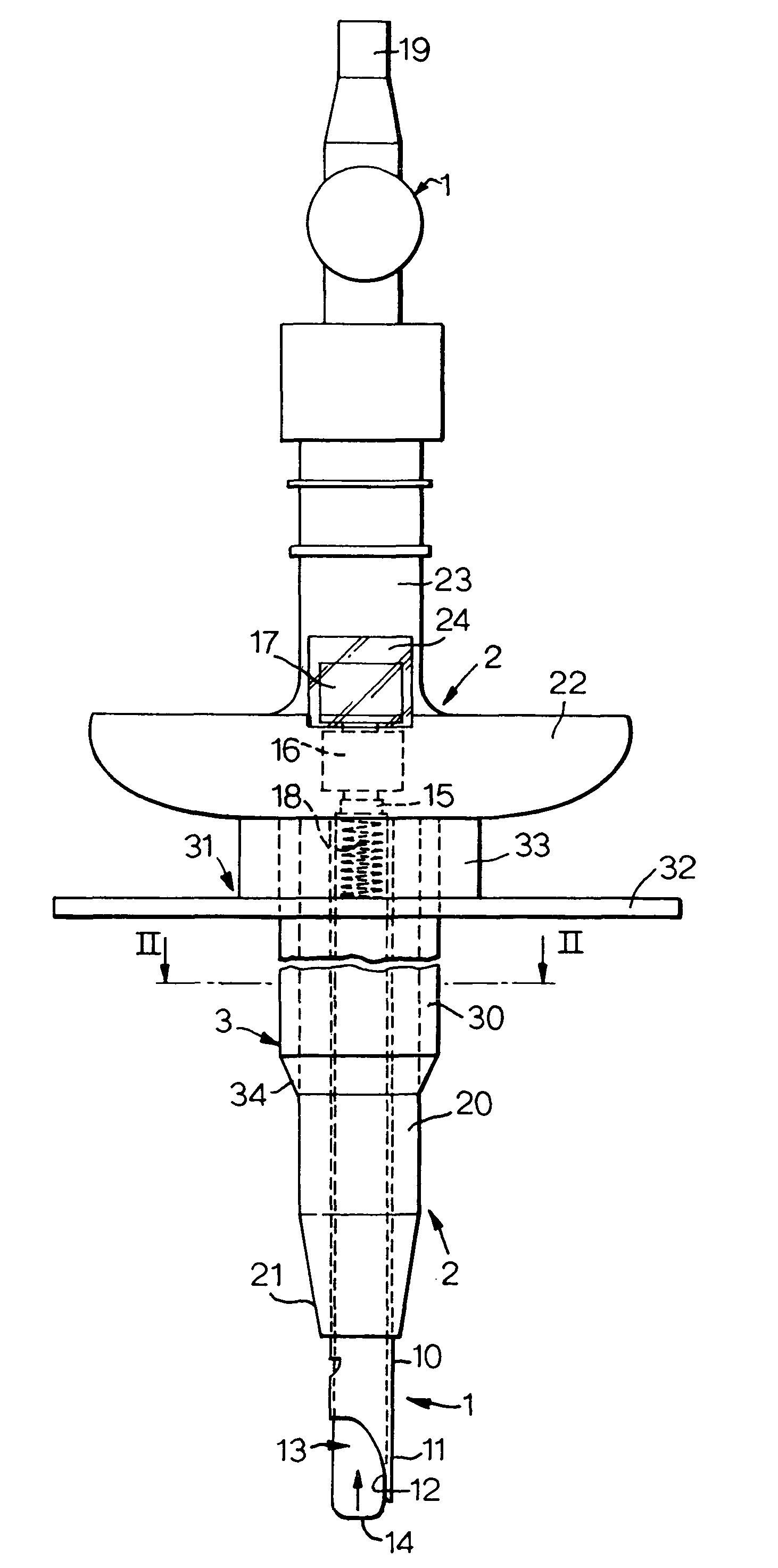
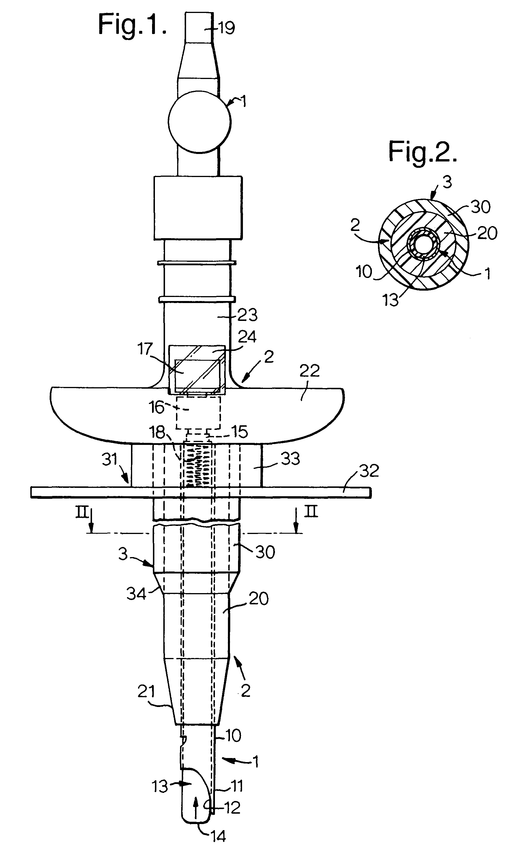
[0014]With reference first to FIGS. 1 and 2, the tracheostomy apparatus comprises a needle assembly 1, a dilator assembly 2 mounted on the outside of the needle assembly and a tracheostomy tube 3 mounted on the outside of the dilator assembly. These components are supplied mounted with one another and are used with one another during the initial stage of the tracheostomy procedure.

[0015]The needle assembly 1 is similar to a Veress needle used in chest surgery and laparascopy. The assembly 1 has a straight, rigid steel needle 10 of circular section which opens axially at its patient end 11 through a cutting tip 12. An inner elongate member in the form of a hollow tube 13 extends along the needle 10 as a sliding fit. The tube 13 may be of a rigid plastics material and has a rounded, open forward or patient end 14. The rear end 15 of the tube 13 projects from the needle 10 and carries an indicator in the form of two colored flags 16 and 17 spaced axially of one another. The forward fla...


PUM


Abstract

An instrument for providing ventilation access to the trachea has a hollow needle with a sharp tip, a tube extending within the needle and a spring urging the tube to project a short distance from the patient end of the needle. The rear end of the tube carries two colored flags one of which is visible at a time in a transparent window towards the machine end of the needle. When the patient end of the instrument is pushed through neck tissue overlying the trachea the inner tube is pushed rearwardly so that a flag of one color is visible. When the patient end of the instrument enters the trachea the spring can push the inner tube forwardly so that the other flag is visible. In one embodiment the instrument carries a dilator and tracheostomy tube that can be slid off the needle after penetration. In another embodiment, ventilation equipment is connected to the rear of the inner tube and the patient is ventilated through the instrument itself.

Description

BACKGROUND OF THE INVENTION[0001]This invention relates to medico-surgical instruments.[0002]Various procedures and instruments are used to ventilate patients via the trachea. Tracheostomies can be made by a conventional surgical technique or by a percutaneous technique, which is quicker and more suited to emergency situations. In the usual percutaneous technique a needle is pushed through the skin of the throat into the trachea. Entry of the needle to the trachea is detected by a loss-of-resistance technique involving a syringe filled with air connected to the needle hub. The tip of the needle is blocked while it is passing through the neck tissue so that manual pressure applied to the needle plunger encounters a resistance to movement. When the tip of the needle enters the trachea air can flow and the plunger can move forwardly, enabling entry to be detected. The syringe is then removed and a guidewire is slid along the needle. The needle is then pulled out along the guidewire, le...

Claims


Application Information

Patent Timeline
Patent Type & Authority Patents(United States)
IPC IPC(8): A61M16/00A61B19/00A61B17/24A61M16/04
CPCA61M16/0429A61M16/0472
Inventor GOSTELOW, THOMAS
Owner SMITHS MEDICAL INT
Why Eureka
Try Eureka