
Apparatus and method for electroplating a metallic film on a rocket engine combustion chamber component

a technology of combustion chamber and metallic film, which is applied in the direction of electrolysis process, electrolysis components, etc., can solve the problems of significant amount of plating solution waste, significant amount of current required, and labor intensive and time-consuming, so as to reduce the volume of typically hazardous plating and reduce the size of the facility and equipment. , the effect of reducing the volume of typical hazardous plating

Active Publication Date: 2007-12-11
THE BOEING CO
View PDF8 Cites 2 Cited by
  • Summary
  • Abstract
  • Description
  • Claims
  • Application Information

AI Technical Summary

Benefits of technology

[0009]The present invention offers significant advantages in the following manifestations: eliminates the need for current ranges in excess of those normally provided by typically standard industrial electrical supply; offers a reduction in the volume of typically hazardous plating solution waste; and, reduces the facility and equipment size and related expenditure required to complete the electrodeposition process on large rocket engine combustion chamber components.

Problems solved by technology

The problem with electrodepositing alloy on large structures such as rocket engine combustion chambers is that a significant amount of current is required.
This is both labor intensive and time consuming.
A tank of this size requires specialized construction and results in a significant amount of plating solution waste.
The '962 patent does not address depositing coatings other than copper and also does not address deposits which require adherence to the cathode part.
U.S. Pat. No 4,659,446 does not address the electrodeposition of metal alloys on the typically conically shaped parts of rocket engine combustion chamber components as well as the deposition of metal alloys on the interior diameter of such components.

Method used


Image

  • Apparatus and method for electroplating a metallic film on a rocket engine combustion chamber component
  • Apparatus and method for electroplating a metallic film on a rocket engine combustion chamber component
  • Apparatus and method for electroplating a metallic film on a rocket engine combustion chamber component

Examples


Embodiment Construction

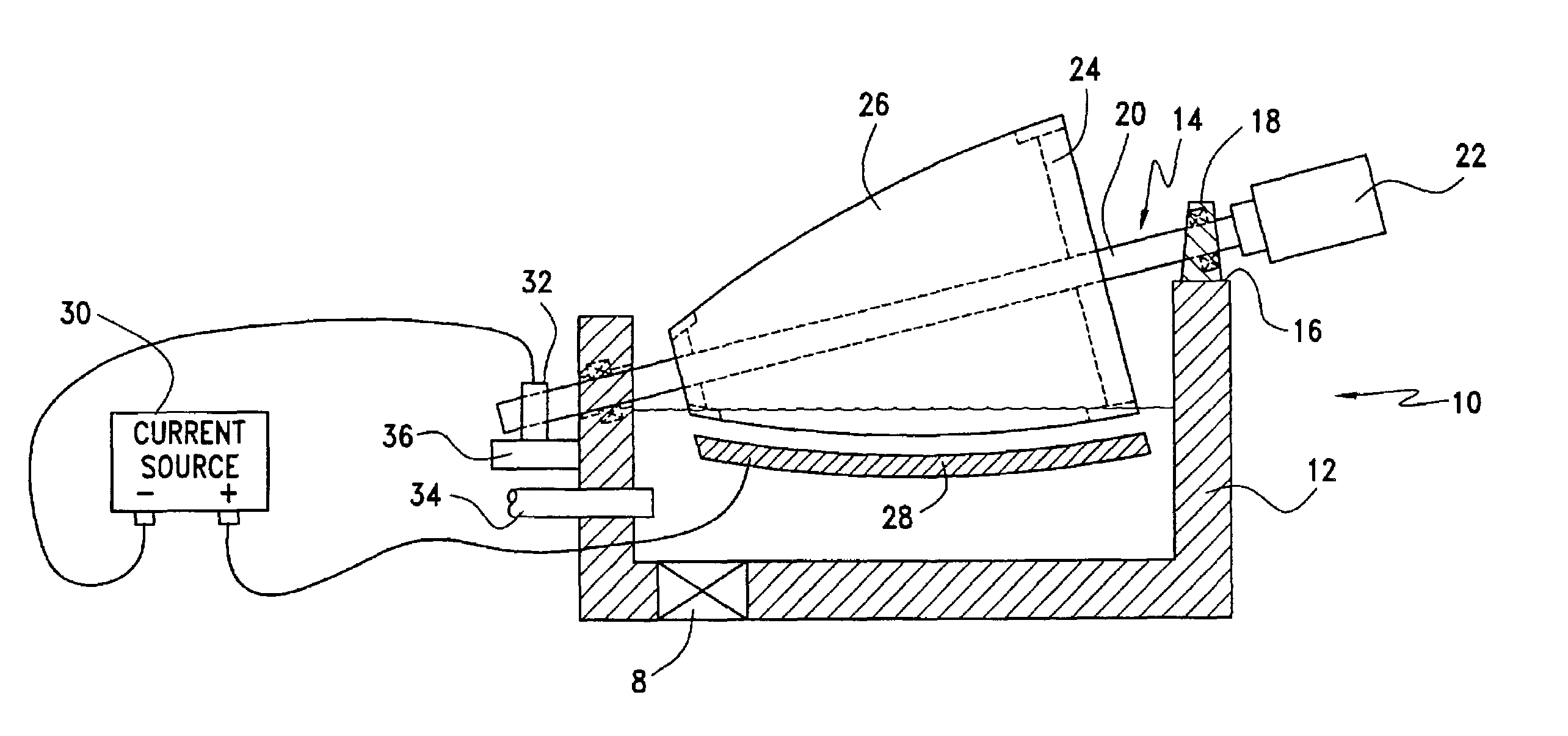
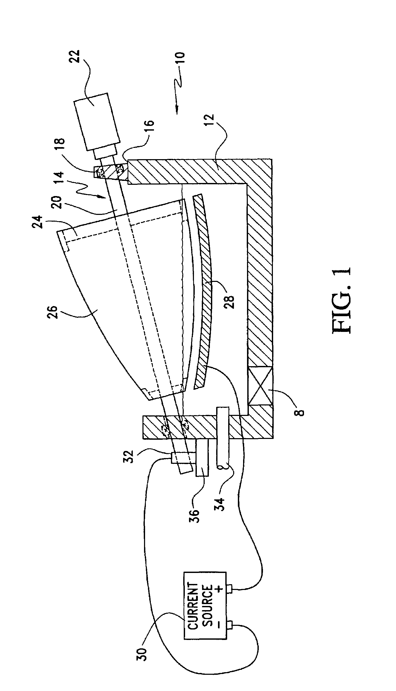
[0014]Referring now to the drawings and the characters of reference marked thereon, FIG. 1 illustrates a first preferred embodiment of the apparatus of the present invention, designated generally as 10. The apparatus 10 includes a tank 12 for containing a plating solution. The tank 12 may be, for example, constructed of a non-conductive acid-resistant material.

[0015]A rotatable support assembly, designated generally as 14, supports a combustion chamber component 26 relative to the tank 12. The rotatable support assembly 14 includes a support member 16 that might include, for example, a section of the tank 12 or a platform or support structure external to the tank. A bearing assembly 18 is supported by the support member 16. A rotatable shaft 20 is supported by the bearing assembly 18. A motor 22 provides the necessary rotation of the shaft 20.

[0016]A support structure 24 supports the combustion chamber component 26 on the rotatable shaft 20. This structure provides support to the co...


PUM

PropertyMeasurementUnit
thicknessaaaaaaaaaa
lengthaaaaaaaaaa
exit diameteraaaaaaaaaa

Abstract

A tank is utilized for containing a plating solution. A rotatable support assembly rotatably supports a combustion chamber component relative to the tank for providing partial immersion of the combustion chamber component within the plating solution. An anode is positioned within the tank proximate a surface of the combustion chamber component to be electroplated. A current source is connected to the anode and in electrical contact with the combustion chamber component. When the combustion chamber component is rotated, the submerged portions are deposited with metal from the plating solution.

Description

BACKGROUND OF THE INVENTION[0001]1. Field of the Invention[0002]The present invention relates to rocket engine combustion chamber fabrication and more particularly to the electrodeposition of metal alloys for the purposes of surface preparation.[0003]2. Description of the Related Art[0004]Large scale combustion chambers are often fabricated from alloys that are not conducive to the brazing operations required to build them. In situations such as this electrodeposited metal alloys are used to create a surface on which the brazing alloy will flow. The problem with electrodepositing alloy on large structures such as rocket engine combustion chambers is that a significant amount of current is required. The amount of current required is a function of the surface area in the plating solution. Currently one of two solutions to this problem exists. The first requires plating the part in sections and requires specialized cells to be fabricated and attached to the part. This is both labor int...

Claims


Application Information

Patent Timeline
Patent Type & Authority Patents(United States)
IPC IPC(8): C25D5/00C25D5/02C25D5/04C25D7/00
CPCC25D7/00C25D5/04
Inventor SCHEPEL, CHAD M.FINT, JEFFRY A.EVANS, STEVE J.FLOWERS, CECIL E.
Owner THE BOEING CO
Learn More