Method of estimating an intersection between at least two continuous signal representations

a continuous signal and estimate technology, applied in the field of establishing an intersection estimate between two functions, can solve the problems of relatively computationally inefficient division operations, low computational efficiency, and low computing cost, and achieve the effects of improving pwm-modulation, computational efficiency, and low harmonic distortion

Inactive Publication Date: 2007-12-11
MUSIC GROUP IP
View PDF4 Cites 4 Cited by
  • Summary
  • Abstract
  • Description
  • Claims
  • Application Information

AI Technical Summary

Benefits of technology

[0021]According to an embodiment of the invention, a simple iterative call of the established continuous signal representation, e.g. an interpolation polynomial, will provide the desired intersection. It should be noted that the established estimate may be provided without any complicated root solving and avoiding division and even square root.
[0043]According to a preferred embodiment of the invention, the input of an iteration may preferably comprise the output of the previous iteration. In this way, an iteration converging towards the intersection may be established.
[0046]One way of obtaining such a mirror function is quite straightforward and illustrated in the specification, i.e. applying a sawtooth signal as reference signal and where sawtooth signal has the gradient numerically equals 1. In this way the mirror function may be established as the inverse function of the non-linear signal representation may easily be found by applying the output (=y−value) of a previous iteration step on the non-linear signal representation and applying this as the input (=x−value) of the next iteration on the non-linear signal representation. This switching between the non-linear signal representation and the inverse function may be repeated as long as it is necessary.
[0070]According to a preferred embodiment of the invention, at least one or some of the performed iterations are performed on reduced polynomial models. These iterations will advantageously comprise the initial or some of the initial iterations of the complete iteration process. According to a very preferred embodiment of the invention, the complete iteration process comprises two iterations on a polynomial model, where the first iteration is performed by means of a reduced polynomial model and the second is performed on a complete polynomial or at least a more detailed polynomial. A reduced polynomial may for instance comprise a 2nd order polynomial of a signal, where the 2nd order component has been omitted. Surprisingly, this “model-truncation” of the 2nd order component reduces the final 3rd order distortion combined with reduced computation.
[0076]According to an embodiment of the invention, the recursive calls may be terminated after a fixed number of recursive iterations. In this way, complicated stop-criteria may be avoided, and moreover, the calculated intersection estimate may be obtained within a predictable time limit.

Problems solved by technology

A well-known problem related to uniform pulse width modulation, UPWM, is that the input signal, due to its discrete nature, may basically not necessarily be represented at the time of intersection.
A problem of many of the relatively new and improved LPWM-techniques is that the resulting improvement is relatively costly with respect to computing requirements.
Typically, prior art LPWM-techniques either do not include an algorithm to determine the pulse width, or they disadvantageously require a division operation to compute the pulse width.
Division operations are relatively computationally inefficient in digital signal processing and require many more computation steps than for example addition or multiplication operations.
Generally known implementations do not provide computationally efficient methods to reduce harmonic distortion in pulse width modulated systems.

Method used


Image

  • Method of estimating an intersection between at least two continuous signal representations
  • Method of estimating an intersection between at least two continuous signal representations
  • Method of estimating an intersection between at least two continuous signal representations

Examples


Embodiment Construction

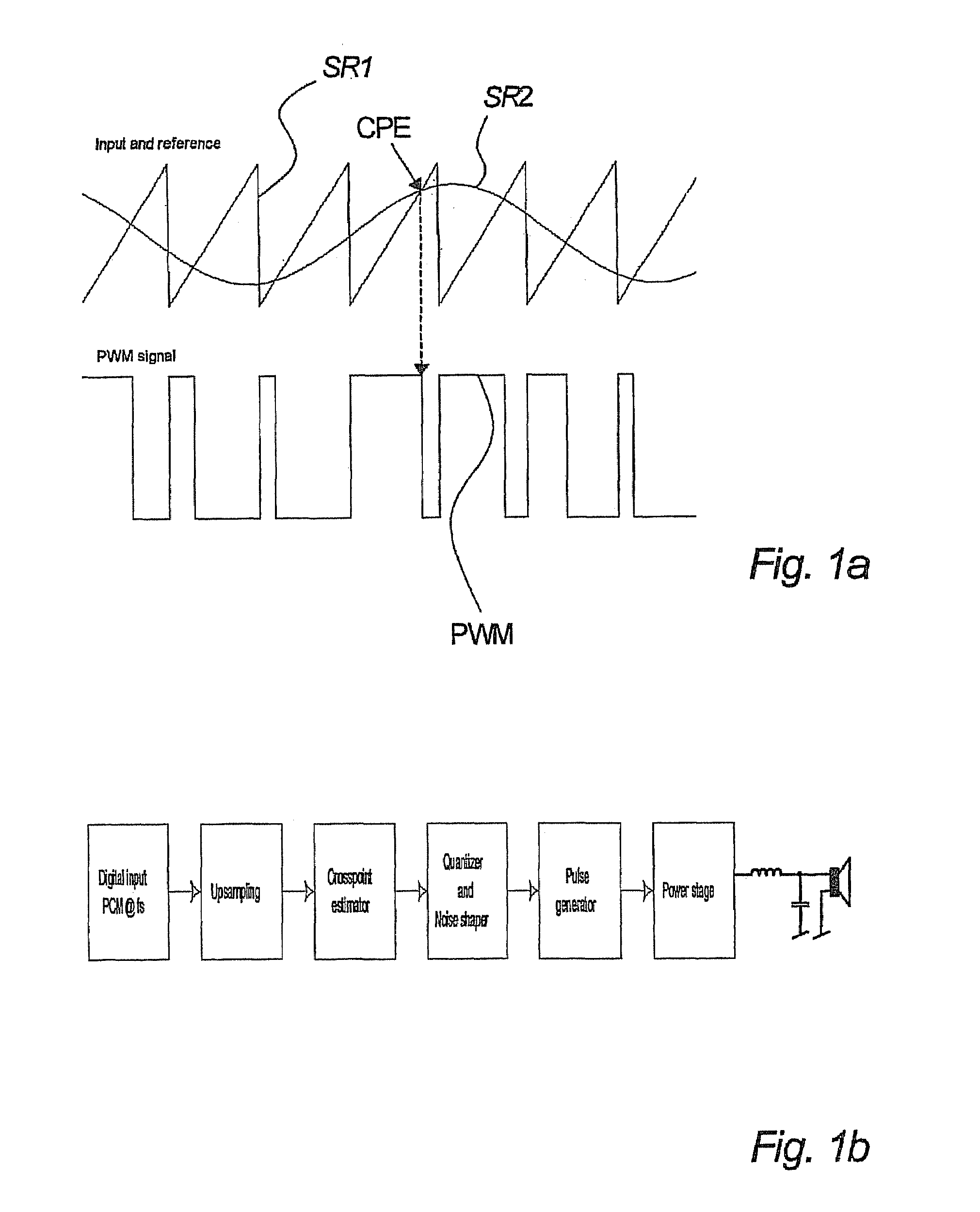
[0129]FIG. 1a and 1b illustrate the basic properties and the nature of PWM modulation.

[0130]It should be noted that the invention in general might be regarded as the establishment of an intersection estimate between at least two curves by means of computer calculations, where at least one of the curves is a non-linear function. One of several applications is within PWM (pulse width modulation) modulation, and the following explanation refers to an application within this technical field.

[0131]The two signal representative curves SR1 and SR2 represent a PWM reference signal and a PWM input signal, respectively.

[0132]In the time continuous domain a PWM signal, i.e. the signal of FIG. 1b is obtained by comparing the input signal representation with e.g. the output of a sawtooth generator. When the input signal is higher than the reference signal representation SR1, here a sawtooth, the PWM output is high and when the input signal is lower than the reference, the PWM output is low.

[0133...


PUM


Abstract

The invention relates to a method of estimating an intersection between at least two continuous signal representations (SR1, SR2) in a pulse width modulator, at least one of said continuous signal representations (SR1, SR2) being non-linear, said method comprising the step of providing an intersection estimate (CPE) between said at least two continuous signal representations on the basis of at least one iteration comprising at least one iterative call of a function describing said continuous signal representations (SR1, SR2) being non-linear and whereby said estimating of intersections are performed in a pulse width modulation modulator. According to an embodiment of the invention, a simple iterative call of the established continuous signal representation, e.g. an interpolation polynomial, will provide the desired intersection. It should be noted that the established estimate might be provided without any complicated root solving and avoiding division and even square root.

Description

FIELD OF THE INVENTION[0001]The present invention relates to a method of establishing an intersection estimate between two functions.BACKGROUND OF THE INVENTION[0002]Pulse width modulation, PWM, is used widely within the field of for instance audio amplifiers. Generally, the available pulse width modulation techniques may be categorized into typically three different types of pulse width modulation, natural pulse width modulation, NPWM, uniform pulse width modulation, UPWM or linearized pulse width modulation, hereinafter LPWM.[0003]Generally, all pulse width modulation implies the technique of transforming or converting an input signal into an output square wave signal having a certain pulse width, at least partly defined by the input signal by comparison of the input signal to a reference signal.[0004]A short review of the general understanding of the above-mentioned groups of pulse width modulation techniques will be given below.[0005]Natural pulse width modulation, NPWM, typical...

Claims


Application Information

Patent Timeline
Patent Type & Authority Patents(United States)
IPC IPC(8): H03K7/08H03F3/217H03M1/82
CPCH03F1/32H03F3/2175H03K7/08H03M1/0614H03F2200/03H03M1/825H03F2200/351
Inventor PEDERSEN, KIM RISHOJARKNAES-PEDERSEN, LARS
Owner MUSIC GROUP IP
Why Eureka
Try Eureka