Error correction for RLL channel bits in demodulation rules

a demodulation rule and error correction technology, applied in the field of error correction methods for rll codes, can solve the problems of code without error correction capability, inability to distinguish between error control coding and channel coding, and inability to correct data sequences

Inactive Publication Date: 2007-12-11
LITE ON IT
View PDF3 Cites 16 Cited by
  • Summary
  • Abstract
  • Description
  • Claims
  • Application Information

AI Technical Summary

Benefits of technology

[0012]According to foregoing descriptions, an objective of the invention is to provide a method for correcting the illegal channel bit sequences of the RLL codeword before the error control code operates. By designing new demodulation rules which merges the mappings between the illegal channel bit sequence and its possible corresponding data sequence into the demodulation table, the present method makes it possible that the receiver end may correct the channel bit error (i.e., the 1T signal in RLL(1,7)) before performing an error control decoding. New demodulation table makes illegal channel bit sequences also associating with data sequences. Therefore, when receives the illegal channel bit sequence, the receiver end may directly decode the illegal channel bit sequence into the associating data sequence as well as decoding a legal channel bit sequence but without increasing any correction logic circuits (i.e., 1T / 2T correction circuits).

Problems solved by technology

Nowadays, though some coding techniques try to combine channel coding and error control coding together, such as continuous phase modulation (CPM), the distinction between error control coding and channel coding becomes more and more unobvious, but it's still under the impression that channel code has no error correction capability.
If the RLL decoder decodes the “illegal” channel bit sequence directly by the original RLL decoding rules, it will result in incorrect data sequence.
The second way which performs 1T error correction before the RLL decoding reduces the error probability effectively, but the costs are that the decoder complexity and the decoding time (because the decoder “1T / 2T correction circuit—” must determine if the received bit sequence contains illegal signal component all the time) is increased.

Method used


Image

  • Error correction for RLL channel bits in demodulation rules
  • Error correction for RLL channel bits in demodulation rules
  • Error correction for RLL channel bits in demodulation rules

Examples


Embodiment Construction

[0025]Some preferred embodiments of the present invention will be described in detail in the following. However, beside the detailed description, the present invention can also be applied widely in other embodiments and the scope of the present invention is only limited by the appended claims.

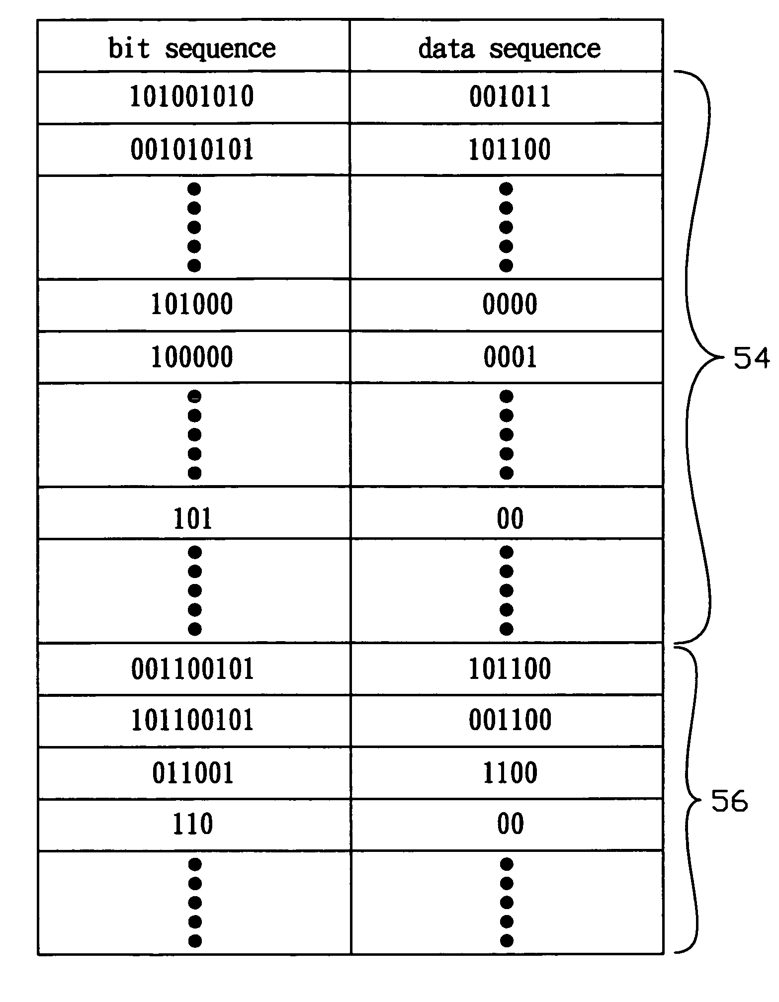
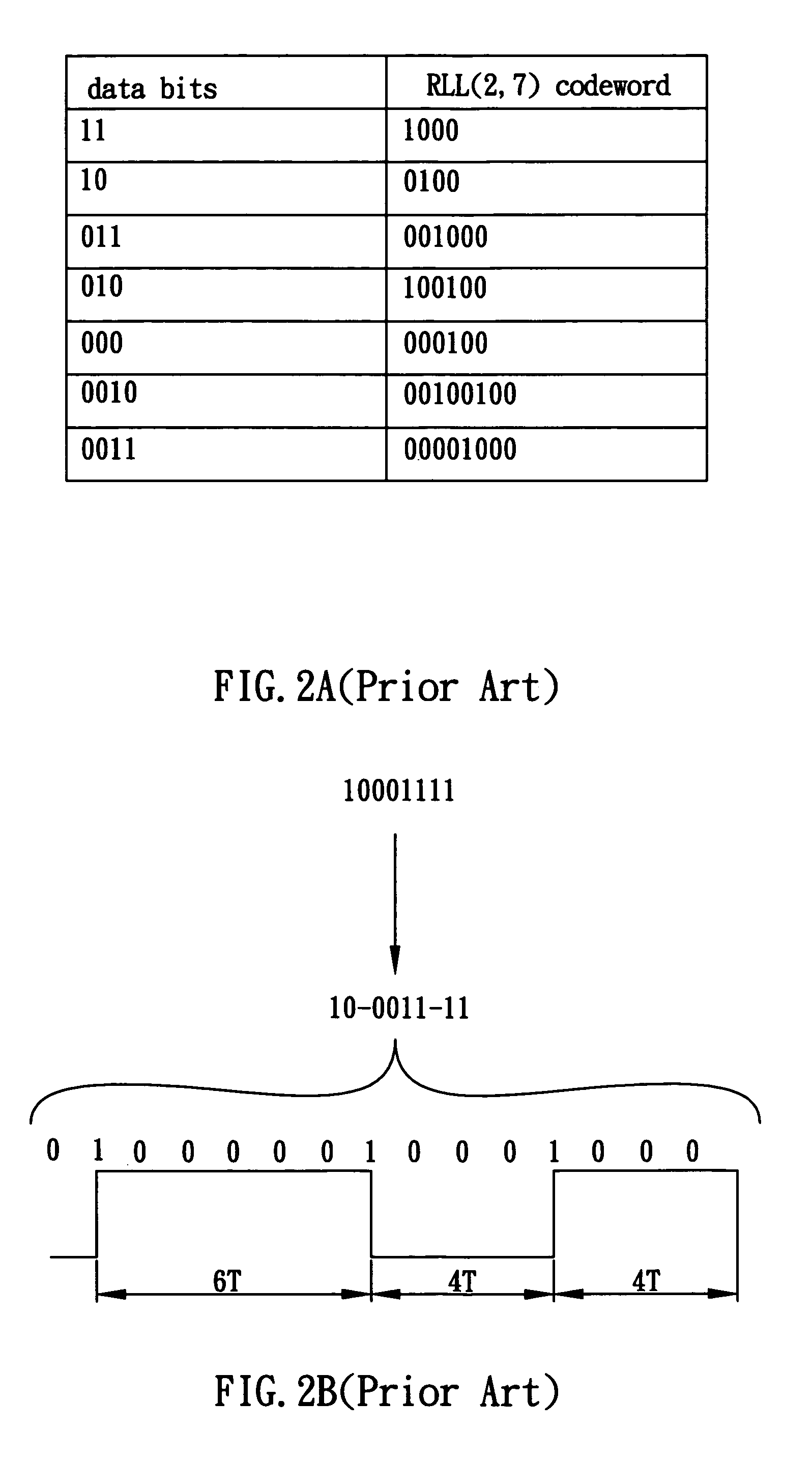
[0026]The legal signal components for a RLL(x,y) encoded codeword are between (x+1)T and (y+1)T. For example, 2T–8T signals are legal, but 1T, 9T, 10T, . . . are illegal for RLL(1,7) code. If a data sequence encodes in RLL(x,y) code, its legal bit sequence should be between (x+1)T to (y+1)T, wherein x, y are natural integers and x is smaller than y. After transmitting to the receiver or reads out from the storage device, the received bit sequence may consist of illegal signal components (i.e., receives 1T signal components for RLL(1,7) encoded bit sequence). In other words, when the legal bit sequence is modulated to a channel, because the channel may induce noise, sometimes the received channe...


PUM


Abstract

RLL (Run Length Limited) code is a well-known channel coding technique, which has no error correction ability itself. The present invention discloses a decoding method, which corrects the channel bit errors via a modified demodulation table with added demodulation rules without increasing any modification circuit, to reduce channel bit errors of RLL code sequences and improve the decoding accuracy of error correction table.

Description

BACKGROUND OF THE INVENTION[0001]1. Field of the Invention[0002]The invention relates to an error correction method for RLL codes. More particularly, the invention relates to correct channel bit error of RLL code with newly added demodulation rules.[0003]2. Description of the Prior Art[0004]Coding plays an important rule in digital systems, especially the digital communication and the data storage system. Generally speaking, coding techniques may divide into three categories: source coding, error control coding, and channel coding. The main purpose of source coding is to transform the information—from human, computer, or whatever—into digital data sequences (especially binary data), furthermore, compress them for reducing information entropy. Error control coding encodes the digital data sequence into a new data sequence that may detect or correct errors, thereby providing error protection for the data sequence. The objective of channel coding is to make the data sequence being able...

Claims


Application Information

Patent Timeline
Patent Type & Authority Patents(United States)
IPC IPC(8): H03M7/00
CPCG11B20/1426H03M5/145G11B20/1833
Inventor LEE, JUI-CHENG
Owner LITE ON IT
Why Eureka
Try Eureka