Method and apparatus for sensory substitution, vision prosthesis, or low-vision enhancement utilizing thermal sensing

Active Publication Date: 2007-12-11
ADVANCED MEDICAL ELECTRONICS
View PDF32 Cites 57 Cited by
  • Summary
  • Abstract
  • Description
  • Claims
  • Application Information

AI Technical Summary

Problems solved by technology

Sensory augmentation and low-vision enhancement devices are only applicable to persons that still have some amount, however limited, of operative vision.
Traditionally, a problem that devices based on each of these methods have in common has been the low effective bandwidth of the information channel.
Audio, haptic, and even retinal stimulation implant devices can only provide a small portion (<1%) of the information bandwidth of a well-functioning eye.
Fundamentally, it is a very complex problem to translate an image in a real world environment into meaningful tactile data.
This level of processing is not very practical in wearable applications.
The use of thermal imaging has not been explored because in the past cryogenically cooled thermal cameras have been too expensive and too bulky to be practical.
It is not presently considered possible for a visible light imager to share the same optics as a thermal imager.
Early thermal imaging systems developed in the 1970s and 1980s were unwieldy and did not lend themselves well to many applications.
P

Method used


Image

  • Method and apparatus for sensory substitution, vision prosthesis, or low-vision enhancement utilizing thermal sensing
  • Method and apparatus for sensory substitution, vision prosthesis, or low-vision enhancement utilizing thermal sensing
  • Method and apparatus for sensory substitution, vision prosthesis, or low-vision enhancement utilizing thermal sensing

Examples


Embodiment Construction

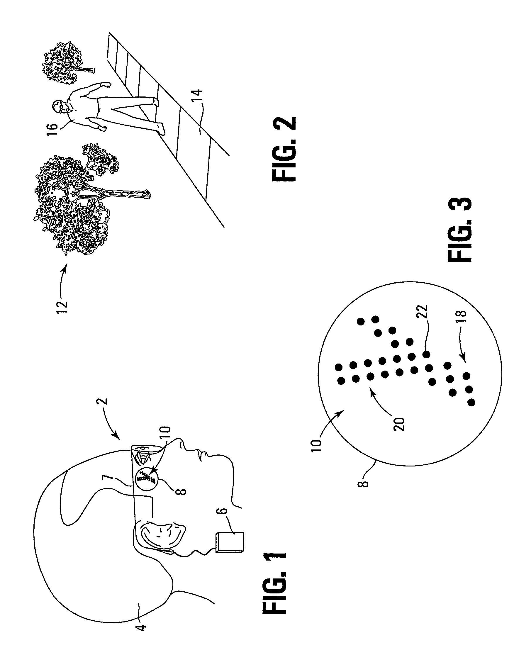
[0047]Newly available infrared sensing, such as infrared microbolometer array technology, is used for thermal imaging by sensing far infrared radiation, according to certain embodiments of the invention. Methods and apparatus for sensory substitution, sensory augmentation, vision prosthesis, or low-vision enhancement according to embodiments of the invention utilize thermal imaging to detect the temperature profile of objects and surroundings.

[0048]From an operational standpoint, seeing the world in temperature instead of visible light causes important shapes to stand out from the background. For example, the shape of a person's or animal's warm body stands out from a typically cooler background—color of clothing makes no difference. Since the temperature of an object is inherently more uniform than all of the possible colors of light, it is easier to translate the thermal image onto a tactile interface that can be touched. With such a system, the size, shape, and activities of peop...


PUM


Abstract

A sensory substitution device according to an embodiment of the invention includes a thermal imaging array for sensing thermal characteristics of an external scene. The device includes a visual prosthesis adapted to receive input based on the scene sensed by the thermal imaging array and to convey information based on the scene to a user of the sensing device. The visual prosthesis is adapted to simultaneously convey to the user different visual information corresponding to portions of the scene having different thermal characteristics. One type of thermal imaging array includes a microbolometer imaging array, and one type of visual prosthesis includes a retinal implant. According to additional embodiments, an apparatus for obtaining thermal data includes a thermal detector adapted to sense thermal characteristics of an environment using a plurality of pixels. The apparatus also includes a pixel translator, operably coupled with the thermal detector, adapted to translate pixel data of the thermal detector to a lower resolution. The apparatus also includes an interface, operably coupled with the pixel translator, adapted to communicate the thermal characteristics of the environment to a user of the apparatus at a lower resolution than sensed by the thermal detector.

Description

CROSS-REFERENCE TO RELATED APPLICATION[0001]The subject matter of this application is related to the subject matter of U.S. Provisional Patent Application No. 60 / 386,036, filed Jun. 6, 2002, which is incorporated herein by reference.STATEMENT OF FEDERALLY SPONSORED RESEARCH AND DEVELOPMENT[0002]This invention was made with government support under Cooperative Agreement No. DAMD17-97-2-7016 awarded by the U.S. Army Medical Research Acquisition Activity to the National Medical Technology Testbed, Inc. The government has certain rights in the invention.BACKGROUND OF THE INVENTION[0003]1. Field of the Invention[0004]Embodiments of the present invention relate to electronic aids for the blind (or individuals with low vision) and prosthetic vision. Thermal imaging is disclosed as an alternative to or enhancement to visible imaging, resulting in an improved interpretation of an observed scene.[0005]2. Description of Related Art[0006]It is estimated that 120,000 Americans are totally blind ...

Claims


Application Information

Patent Timeline
IPC IPC(8): A61N1/36A61F9/08
CPCA61N1/36046A61F9/08
Inventor HAVEY, GARY DAVIDGIBSON, PAUL LORNSEIFERT, GREGORY JOHNKALPIN, SCOTT
Owner ADVANCED MEDICAL ELECTRONICS
Why Eureka
Try Eureka