Collection device

a collection device and cap technology, applied in the field of caps, can solve the problems of false positives, another opportunity for contamination, and exposure of practitioners to harmful pathogens present in fluid samples, so as to improve the volume accuracy of fluid samples, reduce frictional forces, and improve volume accuracy

Inactive Publication Date: 2007-12-18
GEN PROBE INC
View PDF178 Cites 63 Cited by
  • Summary
  • Abstract
  • Description
  • Claims
  • Application Information

AI Technical Summary

Benefits of technology

[0012]In another alternative aspect, the cap of the present invention includes one or more ribs which extend outwardly from the inner surface of the conical inner wall. These ribs can help to form passageways between an outer surface of a fluid transfer device and the inner surface of the conical inner wall of the cap. Furthermore, these ribs will typically minimize the surface area of the cap which comes into contact with a penetrating fluid transfer device, thereby limiting frictional interference between the fluid transfer device and the cap as the fluid transfer device is being withdrawn from a penetrated cap.
[0035]In a twenty-first embodiment of the present invention, a method is provided for containing an aerosol substantially inside of a collection device after a cap associated with the collection device has been penetrated by a fluid transfer device, such as a plastic pipette tip, where the cap contains a wick. Penetration of the cap results in the formation of at least one passageway which may be partially open during penetration of the cap by the fluid transfer device and / or during removal of the fluid transfer device from the collection device. The wick, therefore, may aid in containing an aerosol within the collection device (either partially or completely) as the fluid transfer device is entering an interior chamber of the collection device, as the fluid transfer device is being withdrawn from the collection device and / or after the fluid transfer device has been completely withdrawn from the collection device. The material selected for the wick, and its arrangement inside of the cap, should be such that the material will not substantially impede movement of the fluid transfer device into or out of the collection device. This method is particularly useful when the collection device contains a fluid sample suspected of having a target nucleic acid analyte which will be subsequently amplified using any known amplification procedure prior to a detection step.

Problems solved by technology

While a leak-proof seal should prevent specimen seepage during transport, the physical removal of the cap from the vessel prior to specimen analysis presents another opportunity for contamination.
When removing the cap, specimen which may have collected on the under-side of the cap during transport could come into contact with a practitioner, possibly exposing the practitioner to harmful pathogens present in the fluid sample.
Another risk is the potential for creating a contaminating aerosol when the cap and the vessel are physically separated from one another, possibly leading to false positives or exaggerated results in other specimens being simultaneously or subsequently assayed in the same general work area through cross-contamination.
Since amplification is intended to enhance assay sensitivity by increasing the quantity of targeted nucleic acid sequences present in a specimen, transferring even a minute amount of pathogen-bearing specimen from another container, or target nucleic acid from a positive control sample, to an otherwise negative specimen could result in a false-positive result.
Without such means, a pressurized movement of air from the collection device into the surrounding environment could promote the formation and release of potentially harmful or contaminating aerosols, or bubbles in those instances where proteins or surfactants are present in the fluid sample.

Method used


Image

  • Collection device
  • Collection device
  • Collection device

Examples


example

[0127]To determine the amount of force needed to penetrate a cap 20A-C of the present invention, a Universal Tension / Compression Tester (“Compression Tester”), Model No. TCD 200, and a force gauge, Model No. DFGS-50, were obtained from John Chatillon & Sons, Inc. of Greensboro, N.C. Because the Compression Tester is an automated instrument, it allows for greater reproducibility when determining the compression needed to penetrate a cap that may not be possible following a purely manual approach.

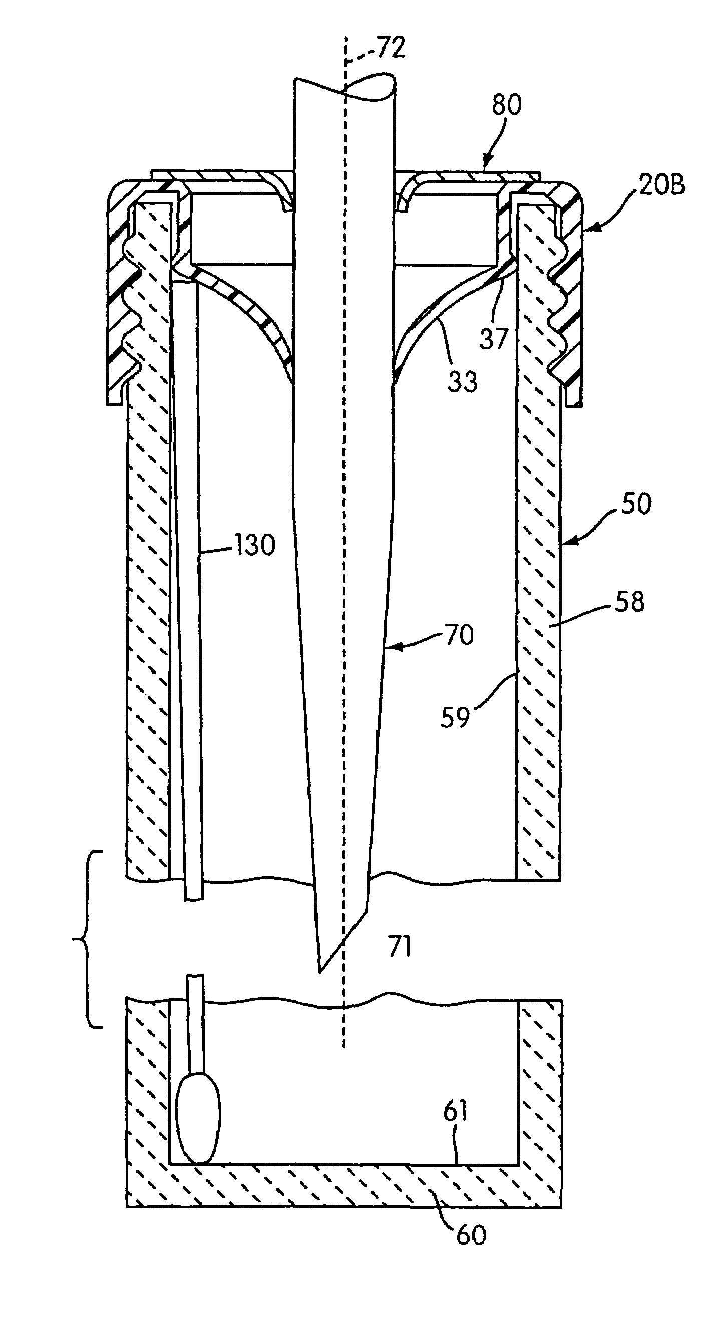
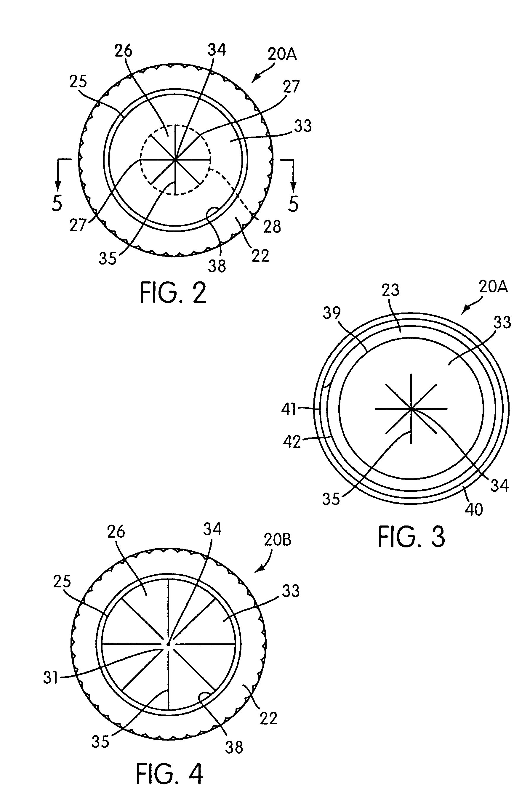
[0128]All caps 20A-C used in this test were made of HDPE and had a substantially uniform thickness of between about 0.0109 inches (0.277 mm) and about 0.0140 inches (0.356 mm), except in the region of the striations 35. The depth of the conical inner wall 33 of the cap 20A-C was about 0.29 inches (7.37 mm) as measured along the longitudinal axis 30 of the cap from the plane of the outer circumference 38 of the conical inner wall 33 to the apex 34 of the same. The diameter of the outer circumf...


PUM


Abstract

A collection device comprising an open-ended vessel for receiving and holding a fluid substance and a cap configured to position a specimen retrieval device along an inner surface of the vessel when the cap is fixedly associated the vessel.

Description

CROSS-REFERENCE TO RELATED APPLICATIONS[0001]This application is a divisional of application Ser. No. 09 / 821,486, filed Mar. 29, 2001, now U.S. Pat. No. 6,206,094, the contents of which are hereby incorporated by reference herein, which is a continuation of application Ser. No. 09 / 704,210, filed Nov. 1, 2000, now U.S. Pat. No. 6,716,396, which is a continuation-in-part of application Ser. No. 09 / 675,641, filed Sep. 29, 2000, now abandoned, which is a continuation-in-part of application Ser. No. 09 / 570,124, filed May 12, 2000, now abandoned, which claims the benefit of U.S. Provisional Application No. 60 / 134,265, filed May 14, 1999.FIELD OF THE INVENTION[0002]The present invention relates to caps for use in combination with fluid-holding vessels, such as those designed to receive and retain biological specimens for clinical analysis and patient monitoring or diagnosis. In particular, the present invention relates to a cap which is penetrable by a fluid transfer device used to transfe...

Claims


Application Information

Patent Timeline
Patent Type & Authority Patents(United States)
IPC IPC(8): B01L3/00B01L3/02B01L3/14B01L99/00G01N35/10
CPCB01L3/0275B01L3/50825G01N35/1079Y10T436/2575B01L2200/026B01L2200/0684B01L2200/141B01L2300/042B01L2300/044B01L2300/046B01L2300/047B01L2300/048B01L2300/0609B01L2300/069Y10T436/25125Y10T436/25Y10T436/25375B01L3/5029
Inventor ANDERSON, BRUCE W.CARTER, NICK M.IHEME, MORDI I.KACIAN, DANIEL L.
Owner GEN PROBE INC
Why Eureka
Try Eureka