Device for reducing the jet noise of a turbomachine

a technology of turbomachine and jet noise, which is applied in the direction of vessel construction, marine propulsion, aircraft navigation control, etc., can solve the problems of degrading the aerodynamic performance of the nozzle, the nozzle is not suitable for transonic flow, and the effect of reducing the jet noise and reducing the drawbacks

Active Publication Date: 2007-12-25
SN DETUDE & DE CONSTR DE MOTEURS DAVIATION S N E C M A
View PDF11 Cites 19 Cited by
  • Summary
  • Abstract
  • Description
  • Claims
  • Application Information

AI Technical Summary

Benefits of technology

[0006]The present invention thus seeks to mitigate such drawbacks by proposing a device for a turbomachine nozzle that enables jet noise to be reduced considerably, in particular for flows at transonic speeds, but without thereby degrading the aerodynamic performance of the nozzle.
[0007]To this end, the present invention provides a device for reducing the jet noise of a turbomachine, said turbomachine having a longitudinal axis and a substantially cylindrical nozzle extending along said longitudinal axis of the turbomachine, having a downstream end for mixing the flows of gas inside and outside said nozzle, said device comprising a plurality of corrugations disposed to extend the downstream end of the nozzle, and a plurality of notches disposed between pairs of successive corrugations in said plurality of corrugations, wherein said plurality of corrugations and said plurality of notches are symmetrical relative to at least one axis perpendicular to said longitudinal axis of the turbomachine so as to generate a dual counter-rotating effect between said gas flows.
[0008]The particular shape of the corrugations which are both twisted and three-dimensional, leads to a dual counter-rotating effect making it possible to increase mixing between the flows and thus to obtain an effective reduction in jet noise without degrading aerodynamic performance. This shape makes it possible to generate tangential shear between the flows in addition to the radial shear, thereby increasing mixing between the flows.

Problems solved by technology

However, that type of lobed nozzle has little effect on reducing jet noise and it is not suitable for flows at transonic speeds.
The slopes of the lobes are too great for such speeds, thereby giving rise to flow separation which degrades the aerodynamic performance of the nozzle.
Although that does reduce jet noise, installing such chevrons also tends to degrade the aerodynamic performance of the nozzle.

Method used


Image

  • Device for reducing the jet noise of a turbomachine
  • Device for reducing the jet noise of a turbomachine
  • Device for reducing the jet noise of a turbomachine

Examples


Embodiment Construction

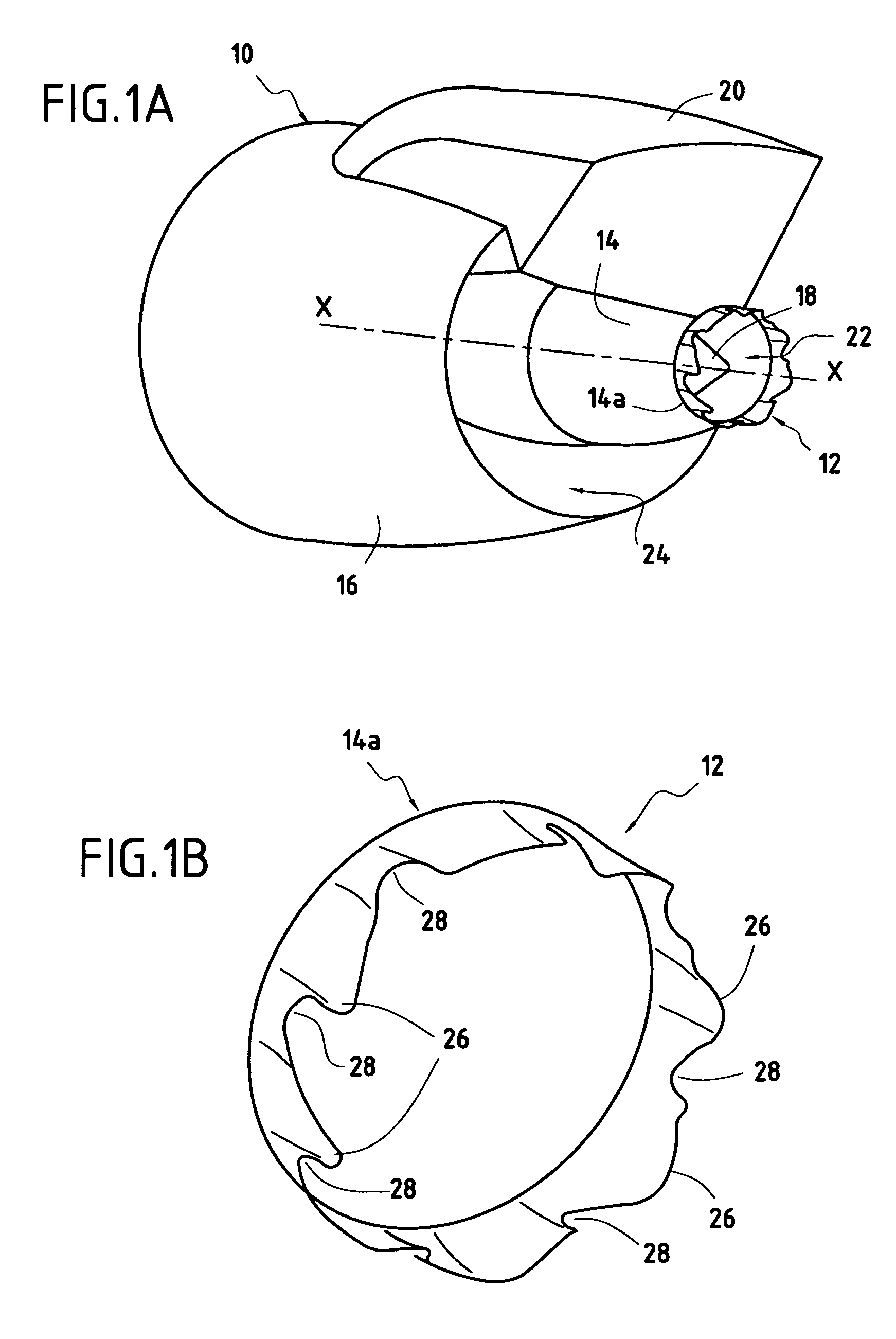
[0015]FIG. 1A is a perspective view of a turbomachine nozzle 10 fitted with a jet noise reduction device 12 of the invention. The nozzle 10 is axially symmetrical in shape about a longitudinal axis X-X of the turbomachine, and is typically constituted by a primary cowl 14, a secondary cowl 16, and a central body 18. The primary cowl 14 is substantially cylindrical or frustoconical in shape, extending along the longitudinal axis X-X. The central body 18 is disposed concentrically inside the primary cowl 14 and is terminated by a portion that is substantially conical.

[0016]In FIG. 1, the downstream end 14a of the primary cowl 14 extends beyond the conical portion of the central body 18. The secondary cowl 16, which is likewise substantially cylindrical or frustoconical in shape, surrounds the primary cowl 14 concentrically. The nozzle as defined in this way is located beneath an airplane wing (not shown in the figures) by means of a support pylon 20.

[0017]The concentric assembly of th...


PUM


Abstract

A device for reducing the jet noise of a turbomachine, the turbomachine having a longitudinal axis and a substantially cylindrical nozzle extending along the longitudinal axis of the turbomachine, having a downstream end for mixing the flows of gas inside and outside the nozzle, the device comprising a plurality of corrugations disposed to extend the downstream end of the nozzle, and a plurality of notches disposed between pairs of successive corrugations in the plurality of corrugations, and the plurality of corrugations and the plurality of notches are symmetrical relative to at least one axis perpendicular to the longitudinal axis of the turbomachine so as to generate a dual counter-rotating effect between the gas flows.

Description

BACKGROUND OF THE INVENTION[0001]The present invention relates to the general field of nozzles fitted to turbomachines. It relates more particularly to reducing the jet noise generated at the outlet from separated flow nozzles of airplane turbomachines, in particular while such airplanes are taking off.[0002]The nozzles fitted to civil airplane turbomachines are generally made up of a central body surrounded by a primary cowl forming between them a first annular channel for a primary flow. A secondary cowl surrounds the primary cowl to form a second annular channel for a secondary flow. Overall such nozzle assemblies are generally axially-symmetrical in shape.[0003]The present invention relates to a device for reducing the jet noise at the outlet from such nozzles, in particular during takeoff when the ejection speeds of the primary and secondary flows are transonic (i.e. about 0.9 Mach), but without thereby degrading aerodynamic performance.[0004]In order to reduce the jet noise ge...

Claims


Application Information

Patent Timeline
Patent Type & Authority Patents(United States)
IPC IPC(8): F02K1/46F02K1/48B64D33/00F02K1/34F02K1/38
CPCF02K1/34F02K1/38F02K1/48F02K1/386F05D2250/71F05D2250/183
Inventor PROUTEAU, JACKIEMIROUDOT, FREDERIC
Owner SN DETUDE & DE CONSTR DE MOTEURS DAVIATION S N E C M A
Why Eureka
Try Eureka