Inlet airflow cooling control for a power generating system

a technology of power generating system and cooling control, which is applied in the direction of engine control, mechanical equipment, machines/engines, etc., can solve the problems of direct refrigeration-cooling system, parasitic power loss, and parasitic power loss as much as thirty percent (30%), and achieve more accurate, reliable temperature sensing, and accurate sense of the temperature of the inlet airflow

Inactive Publication Date: 2007-12-25
SIEMENS ENERGY INC
View PDF18 Cites 20 Cited by
  • Summary
  • Abstract
  • Description
  • Claims
  • Application Information

AI Technical Summary

Benefits of technology

[0011]Another aspect of the present invention relates to a method for controlling the cooling means, such as an evaporative water cooler or fogging system, to maintain inlet airflow at an approach setpoint determined as a function of turbine load. The method may include positioning at least one inlet airflow temperature sensor between the cooling means and the combustion turbine air inlet for sensing a drybulb temperature. The method may also include using the sensed drybulb temperature for controlling the cooling means to maintain the inlet airflow at the approach setpoint. This method allows for controlling the evaporative water cooler or fogging system over a range of transient load conditions during operation of the power generating system.

Problems solved by technology

One drawback to the direct refrigeration-cooling system, however, is parasitic power loss.
This is due to the relatively large power drain needed to power a refrigerator unit.
According to some estimates, the parasitic power loss may be as much as thirty percent (30%) of the increased power output of the turbine power generator.

Method used


Image

  • Inlet airflow cooling control for a power generating system
  • Inlet airflow cooling control for a power generating system
  • Inlet airflow cooling control for a power generating system

Examples


Embodiment Construction

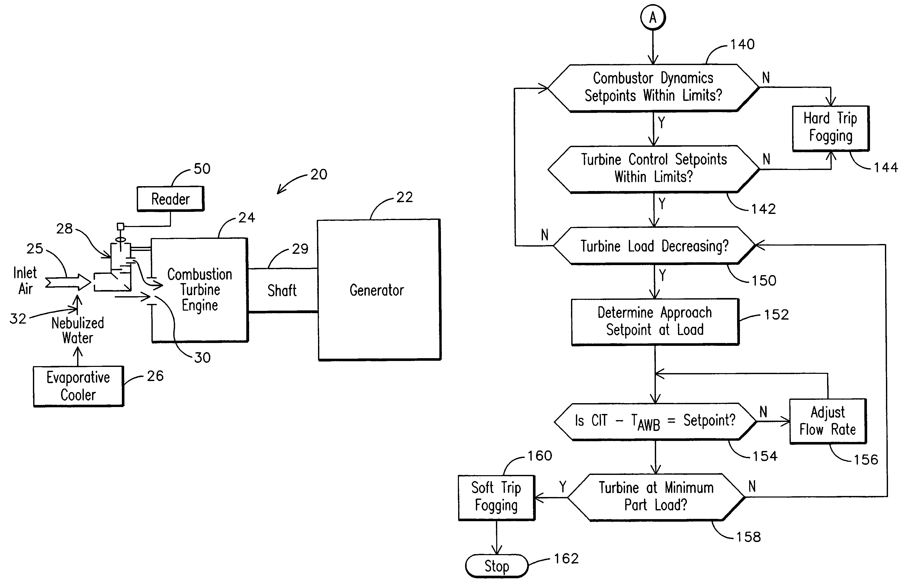
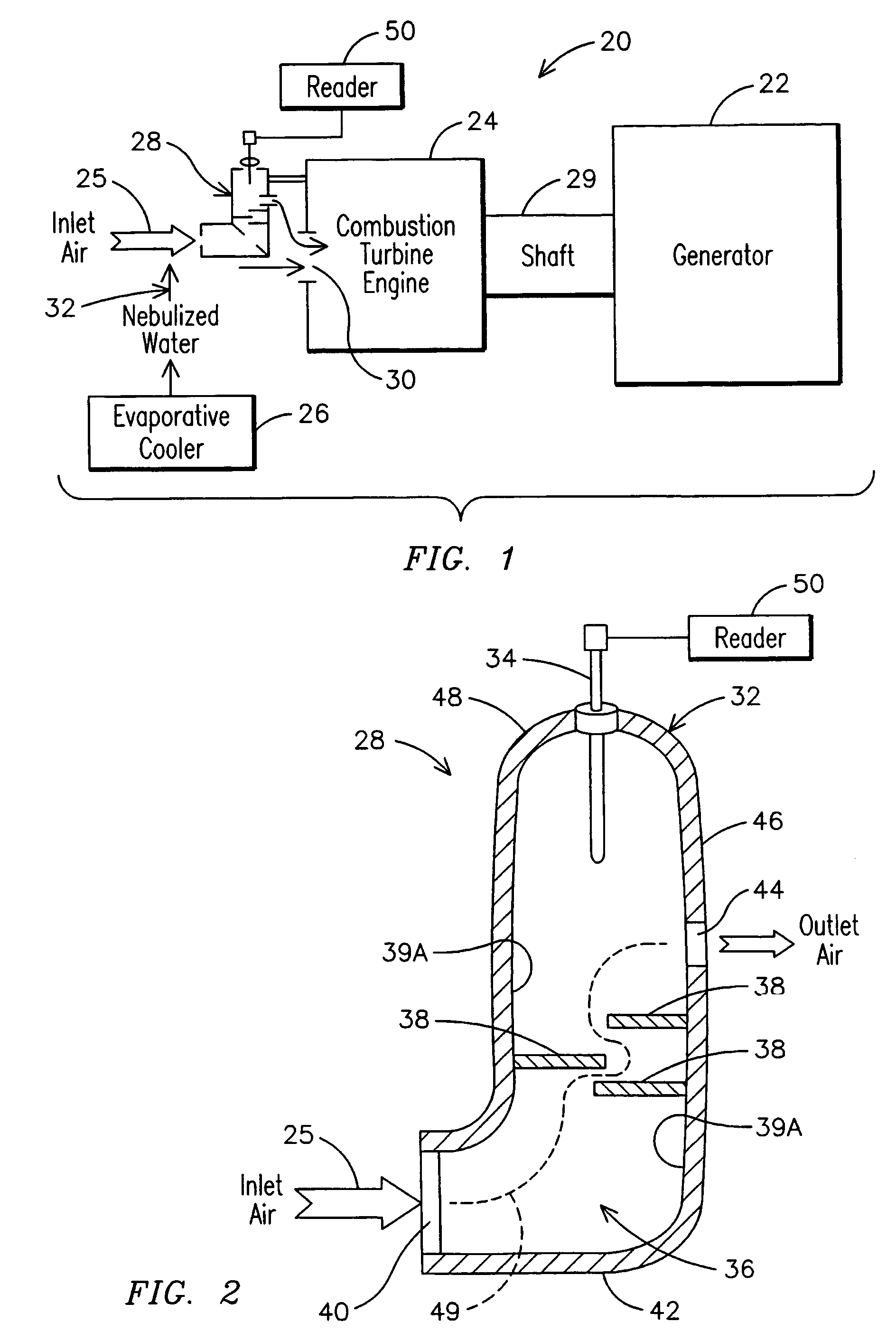
[0022]FIG. 1 illustrates a power generating system or apparatus 20 that may include an inlet airflow temperature sensor 28 in accordance with aspects of the present invention. The power generating apparatus 20 may include a generator 22, a combustion turbine 24 for driving the generator, a means for cooling an inlet airflow 25 received by the combustion turbine, such as evaporative water cooler 26, and a means for sensing the temperature of inlet airflow 25 such as temperature sensor 28.

[0023]The combustion turbine 24 may include a compressor for receiving and compressing inlet airflow 25 comprising ambient air. The combustion turbine 24 may also comprise a combustor for adding fuel to the received inlet air and igniting the mixture, and a turbine that is powered by the expansion of heated gases resulting from combustion of the ignited mixture. The expansion of heated gases powers the turbine 24 to drive a shaft 29 connected to the generator 22. The generator 22 may include a stator...


PUM


Abstract

A power generating system (20) includes a generator (22) and a combustion turbine (24) for driving the generator (22). The combustion turbine (24) may have a combustion turbine air inlet (30) for receiving an inlet airflow (25). The power generating system (20) may include an evaporative water cooler (26) or fogging evaporative system (26′) for cooling inlet airflow (25), and an inlet airflow temperature sensor (28) proximate or within the combustion turbine air inlet (30). The inlet airflow temperature sensor (28) may sense a drybulb temperature of the inlet airflow (25) proximate the air inlet (30). A controller (47′) is provided for controlling the cooling of inlet airflow (25) across transient load conditions of the power generating system (20′). This control may be based upon the sensed drybulb temperature used to calculate an approach temperature with respect to the inlet airflow (25′) that is compared to an approach temperature setpoint based on load. The controller may adjust the flow rate of water of the fogging system (26′) to maintain the calculated approach temperature within limits of the setpoint.

Description

RELATED APPLICATIONS[0001]This application is a continuation-in-part of U.S. patent application Ser. No. 10 / 430,663, filed on May 6, 2003, now U.S. Pat. No. 6,923,003 titled “Power Generating Apparatus Having Combustion Turbine Inlet Air Flow Temperature Sensor For Sensing A Drybulb Temperature and Related Methods” and assigned to the assignee of the present invention, the entire disclosure of which is incorporated herein by reference, which is a continuation-in-part of U.S. patent application Ser. No. 10 / 244,066, filed Sep. 13, 2002 now U.S. Pat. No. 6,775,988, the entire disclosure of which is incorporated herein by reference.BACKGROUND OF THE INVENTION[0002]The present invention relates in general to power generating systems and more particularly to temperature sensing for controlling the cooling of inlet airflow to combustion turbine power generators.[0003]An electrical power generator converts mechanical energy into electrical energy. A typical electrical power generator includ...

Claims


Application Information

Patent Timeline
Patent Type & Authority Patents(United States)
IPC IPC(8): F02C9/00F02C3/30
CPCF02C3/30F05D2270/303Y02E20/16F05D2260/607
Inventor DOVALI-SOLIS, FRANCISCOWILLEMS, DANIEL E.KOZACHUK, DAN W.
Owner SIEMENS ENERGY INC
Why Eureka
Try Eureka