Blood pressure cuffs with resilient support sleeves

a technology support sleeves, applied in the field of blood pressure monitors, can solve the problems of affecting the use of the monitor, the coiled connection of the sensor to the external monitoring device may move, and the sensor itself may not be held in reliably, so as to inhibit slippage during us

Active Publication Date: 2007-12-25
SUNTECH MEDICAL
View PDF31 Cites 14 Cited by
  • Summary
  • Abstract
  • Description
  • Claims
  • Application Information

AI Technical Summary

Benefits of technology

[0010]In certain embodiments, the sleeve may be configured with a rib support member and a sensor-holding chamber. The sensor-holding chamber can hold one or more sensors in a desired orientation and / or position relative to the patient during use. The sensor-holding chamber may be in communication with a curvilinear sensor-holding channel that can be sized and configured to receive, route, and support an associated sensor cable therein. The sensor-holding channel can be curvilinear and configured to provide strain relief support for the cable and / or inhibit sensor movement, which, in turn, can improve the SNR of the monitored signal.
[0013]The sleeve may include a sensor having a cable associated therewith, the sensor held in the sleeve sensor chamber and the sensor cable held in the sensor channel. The sensor is adapted to take a biophysical measurement of a patient during use and the sleeve body has a closed perimeter configuration defining an aperture extending in the axial direction. The sleeve aperture is sized and configured to laterally stretch to receive a predetermined anatomical body extremity, digit, or limb of a patient therein, during use, and the sleeve aperture has a first configuration with a first width during periods of non-use and a second configuration with an expanded second width when in position on a patient. When in the second configuration, the sleeve is substantially conformable to and resides securely against a desired portion of the extremity, digit, or limb of the patient with sufficient compressive force so that it is able to maintain its desired longitudinal position and hold the sensor in a desired location against the patient to thereby inhibit slippage during use.

Problems solved by technology

However, the cable that connects the sensor to the external monitoring device may move or the sensor itself may not be held in reliably snug abutment to the skin and / or over the artery of interest.

Method used


Image

  • Blood pressure cuffs with resilient support sleeves
  • Blood pressure cuffs with resilient support sleeves
  • Blood pressure cuffs with resilient support sleeves

Examples


Embodiment Construction

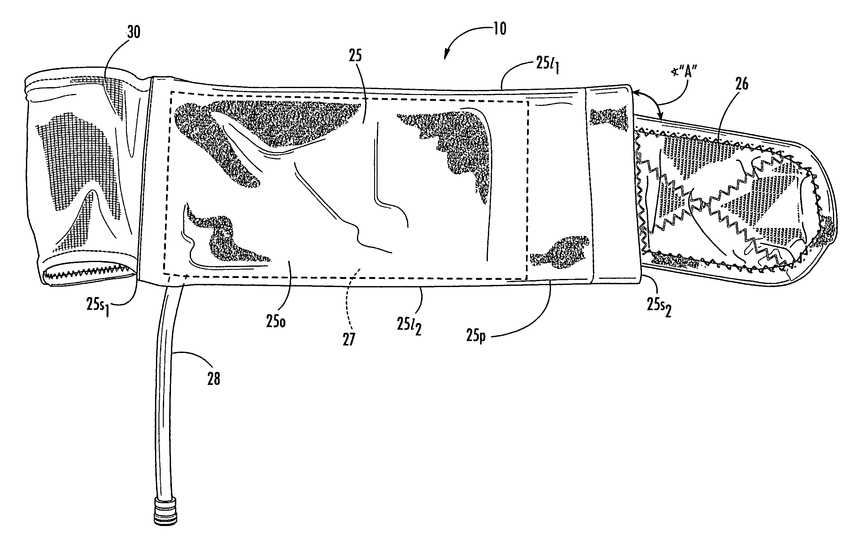
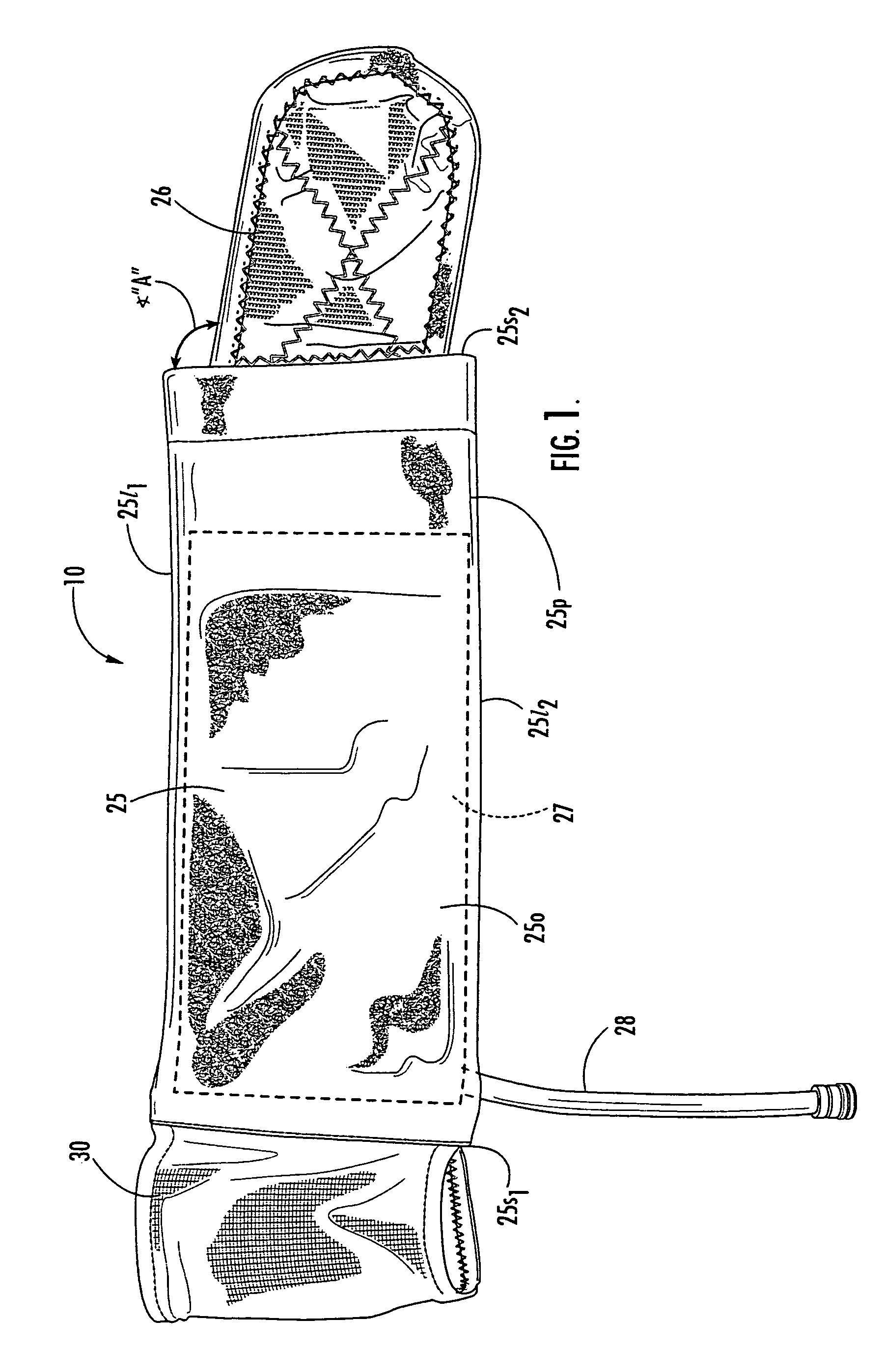
[0008]Certain embodiments of the present invention provide blood pressure cuffs with resilient expandable support sleeves attached to the elongated cuff. Related systems and methods for obtaining blood pressure measurements as well as methods of fabricating blood pressure cuffs and / or sleeves are also described.

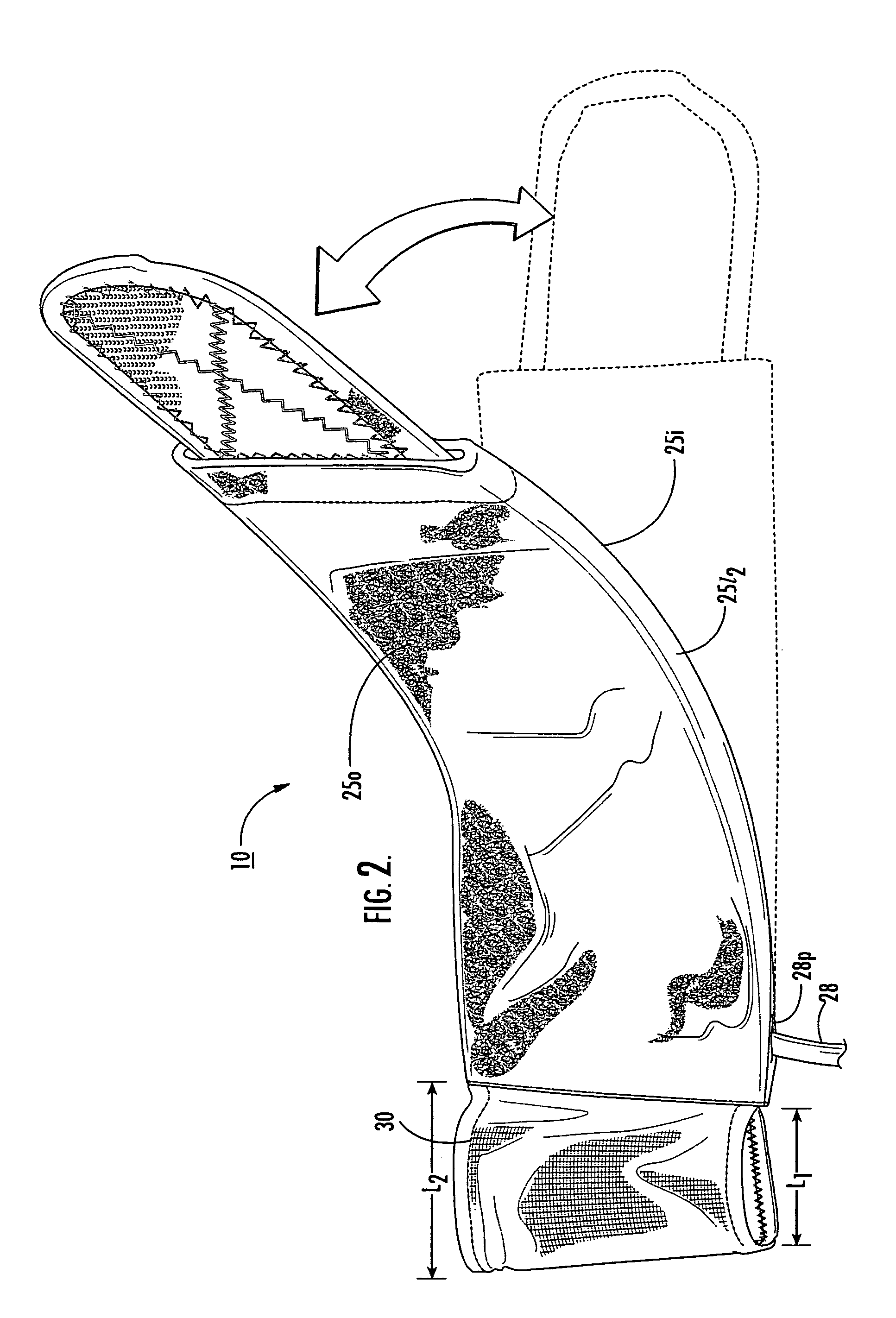
[0009]In certain embodiments, the sleeve can be configured as a resilient breathable fabric in a truncated cone configuration (i.e., “frustoconical” shape). The sleeve can be fabricated to provide stretch in the lateral direction sufficient to support the positioning of the blood pressure cuff on the desired limb. In certain embodiments, the stretch may be a two-way elasticity or stretch, with stretch in the lateral direction being greater than in the longitudinal direction. The sleeve can be attached to an end portion of the elongated cuff. The sleeve attachment may be integrally attached or fixed to the cuff body (for use over a number of patients) or detachable from the cu...


PUM


Abstract

Inflatable blood pressure cuff assemblies include an inflatable elongate cuff member having opposing long edges and opposing short edge portions with a fluid chamber therein and a resilient support sleeve with at least one rib support member, the sleeve attached to a respective one of the opposing short edge portions of the inflatable elongate cuff member. The sleeve may be configured with a sensor chamber and a cable routing channel. Related systems and methods of fabricating cuff assemblies and resilient support sleeves are also described.

Description

RELATED APPLICATIONS[0001]This application is a continuation-in-part of U.S. patent application Ser. No. 10 / 292,174 filed Nov. 12, 2002, now U.S. Pat. No. 6,988,992, the contents of which are hereby incorporated by reference as if recited in full herein.FIELD OF THE INVENTION[0002]The present invention relates to blood pressure monitors and associated inflatable cuffs.BACKGROUND OF THE INVENTION[0003]Blood pressure monitoring systems may be ambulatory or stationary. The systems employ inflatable blood pressure cuffs to obtain blood pressure measurements of patients. In operation, the blood pressure cuff is typically wrapped around a limb (typically the arm) of a patient. The blood pressure cuff is inflated to provide a certain amount of pressure on a major artery in the limb (such as the brachial artery in the arm) so as to restrict the blood flow in the artery; then the pressure is slowly released until a measurement of the systolic / diastolic pressures are obtained.[0004]Convention...

Claims


Application Information

Patent Timeline
Patent Type & Authority Patents(United States)
IPC IPC(8): A61B5/02A61B5/022A61B17/135
CPCA61B5/02233A61B17/135A61B5/7285
Inventor JUST, STEVENGALLICK, DAVIDMCBEE, DAYN
Owner SUNTECH MEDICAL
Why Eureka
Try Eureka