Capillary interconnect device

a capillary interconnect and connector technology, applied in the field of microfluidic systems, can solve the problems of difficult to achieve, difficult to achieve, and unsuitable adhesive bonding for many chemical analysis applications

Inactive Publication Date: 2007-12-25
SANDIA NAT LAB
View PDF43 Cites 66 Cited by
  • Summary
  • Abstract
  • Description
  • Claims
  • Application Information

AI Technical Summary

Problems solved by technology

The physical stresses placed on these connectors can be demanding.
However, because of the extremely small tolerances involved this has been difficult to achieve.
Adhesive bonding is unsuitable for many chemical analysis applications because the solvents used attack the adhesive which can lead to channel clogging, detachment of the tubing, and/or contamination of the sample and/or reagents in or delivered to the device.
Furthermore, adhesive bonding results in a permanent attachment of the tubing to the microfluidic device which makes it difficult to change components, i.e., either the microfluidic device or the tubing, if necessary.
Thus assembly, repair and maintenance of such devices become labor and time intensive, a particularly undesirable feature when the microfluidic device is used for high throughput screening of samples such as in drug discovery.
However, such a connection typically is unsuitable for high-press...

Method used


Image

  • Capillary interconnect device
  • Capillary interconnect device
  • Capillary interconnect device

Examples


Embodiment Construction

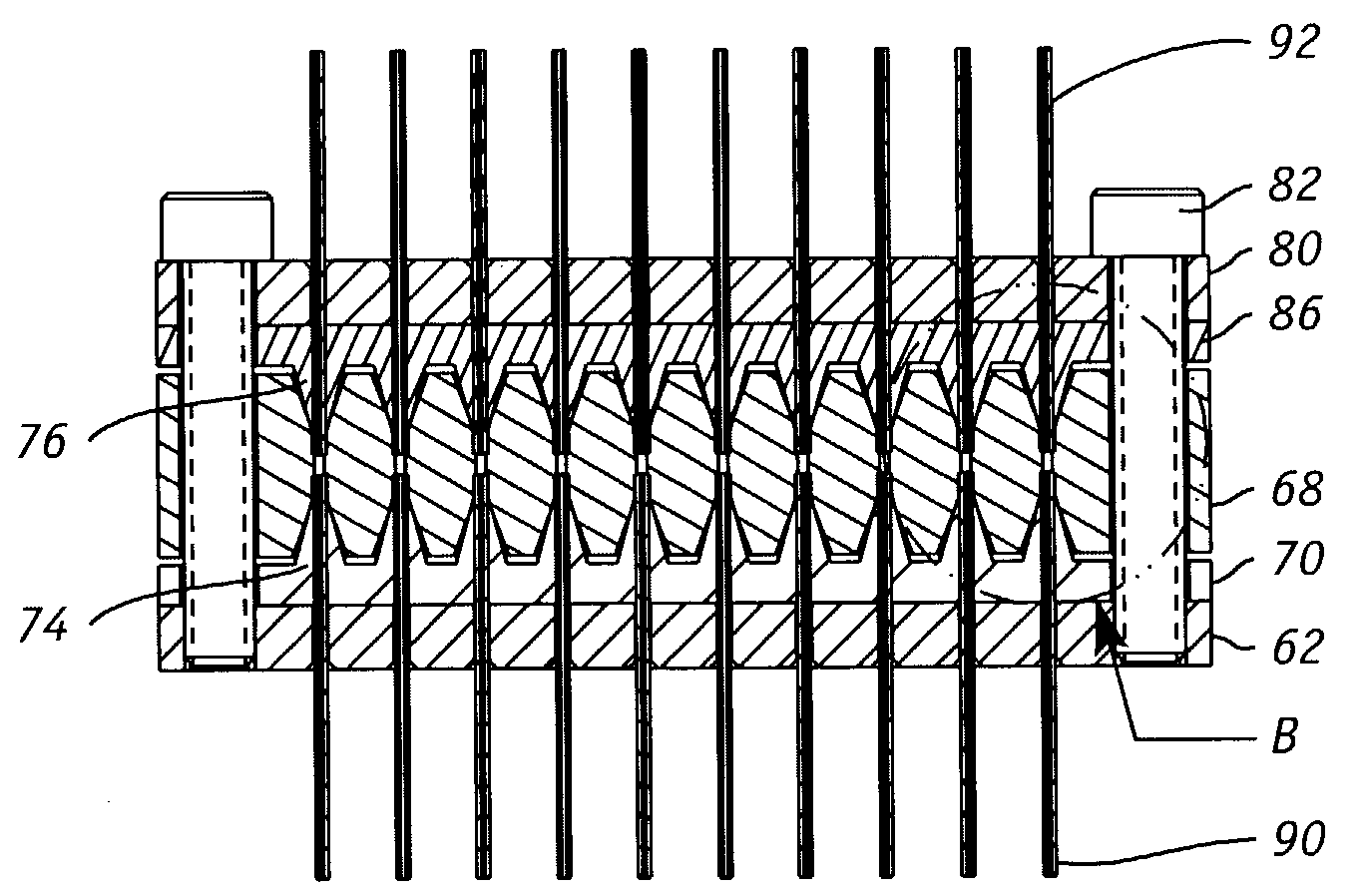
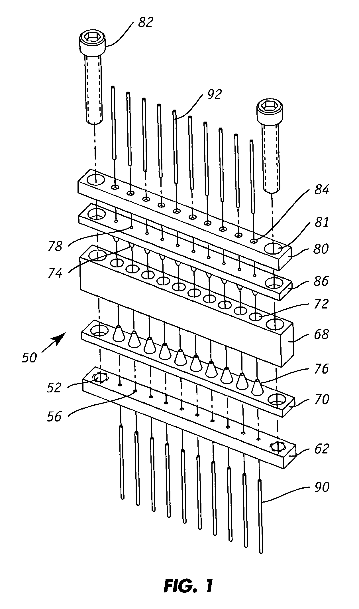
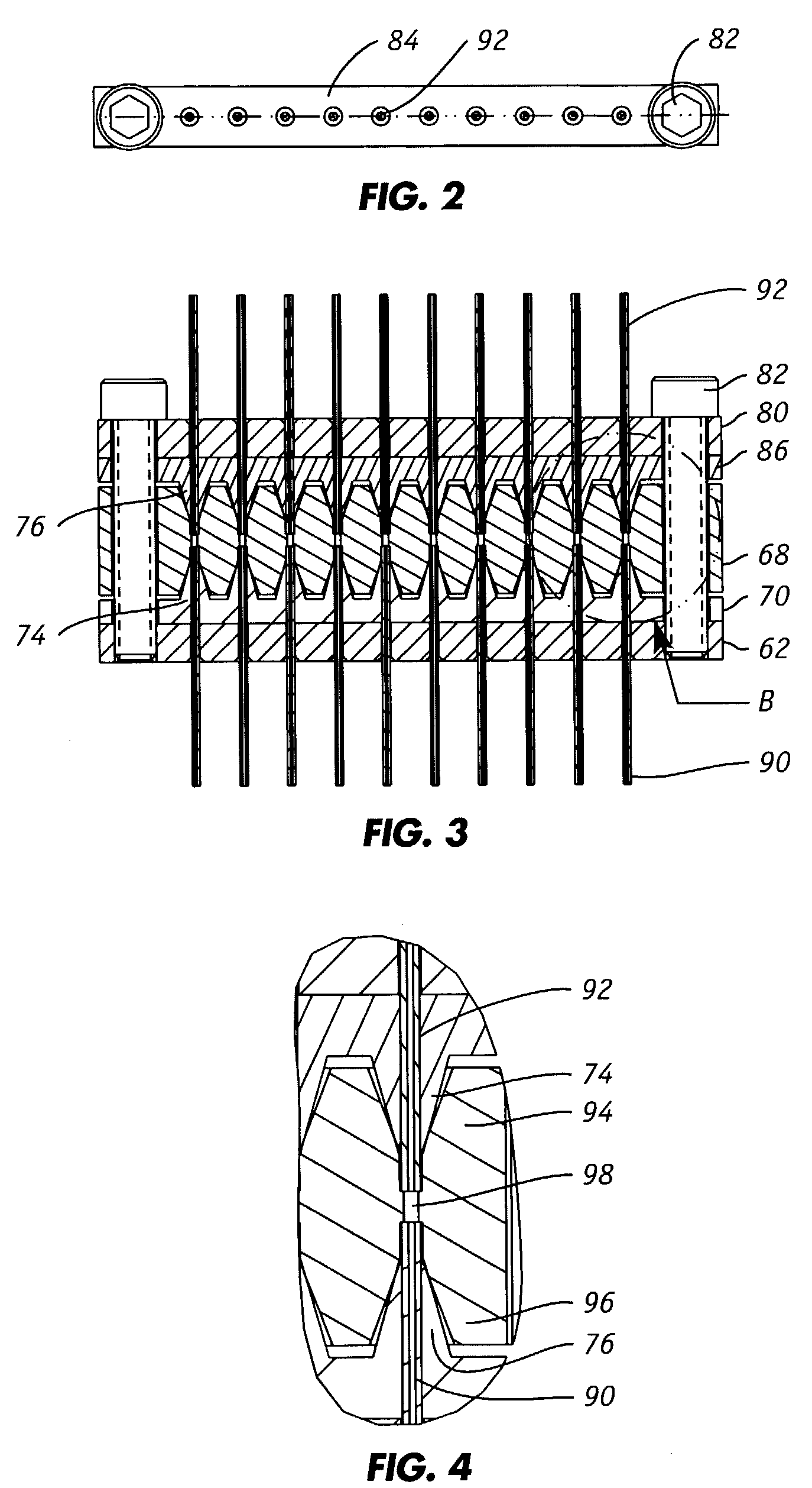
[0034]The invention is directed to techniques for connecting two sets of capillaries together and for connecting capillaries and / or other fluid conduits directly to inlet and / or outlet ports of a microscale device. For convenience, one set will be referred to as the “inlet” capillaries and the other set as the “outlet” capillaries. It is not intended that the structures and dimensions of the inlet and outlet capillaries be different. Preferred capillaries have circular inner diameters that range from 5 microns to 250 microns. Capillaries are available commercially from numerous sources including, for example, Polymicro Technologies LLC (Phoenix, Ariz.).

[0035]The inventive interconnecting device is particularly suited for connecting inlet capillaries to outlet capillaries that are in turn connected to a microfluidic substrate or device. The outlet capillaries, for example, may be connected to sources of chemicals, solvents and other fluids that are delivered to and used in the microf...


PUM


Abstract

A manifold for connecting external capillaries to the inlet and/or outlet ports of a microfluidic device for high pressure applications is provided. The fluid connector for coupling at least one fluid conduit to a corresponding port of a substrate that includes: (i) a manifold comprising one or more channels extending therethrough wherein each channel is at least partially threaded, (ii) one or more threaded ferrules each defining a bore extending therethrough with each ferrule supporting a fluid conduit wherein each ferrule is threaded into a channel of the manifold, (iii) a substrate having one or more ports on its upper surface wherein the substrate is positioned below the manifold so that the one or more ports is aligned with the one or more channels of the manifold, and (iv) means for applying an axial compressive force to the substrate to couple the one or more ports of the substrate to a corresponding proximal end of a fluid conduit.

Description

[0001]This invention was made with Government support under Contract No. DE-AC04-94AL85000 awarded by the U.S. Department of Energy to Sandia Corporation. The Government has certain rights to the invention.FIELD OF THE INVENTION[0002]The present invention relates generally to microfluidic systems and more particularly to structures which facilitate the introduction of fluids into devices having microfluidic channels.BACKGROUND OF THE INVENTION[0003]Microfluidic devices or substrates typically consist of two or more microchannels or capillaries that can range in size from about 5-100 μm wide and 5-100 μm deep etched or molded in a substrate that can be silicon, plastic, quartz, glass, or plastic. Microfluidic substrates may be fabricated using photolithographic techniques similar to those used in the semi-conductor industry, and the resulting devices can be used to perform a variety of sophisticated chemical and biological analytical techniques. Microfluidic analytical technology has...

Claims


Application Information

Patent Timeline
IPC IPC(8): B01L11/00B01L99/00
CPCB01L3/565F16L39/00B01L2200/027G01N2030/185B01L2300/0838
Inventor RENZI, RONALD F.
Owner SANDIA NAT LAB
Why Eureka
Try Eureka