Snare strainer

a strainer and snare technology, applied in the field of snare strainers, can solve the problems of increasing manufacturing costs, difficult to smoothly move the moving base, and easy rattle of the moving base 16/b>, and achieve the effects of reducing the number of parts, high precision, and simple structur

Active Publication Date: 2007-12-25
YAMAHA CORP
View PDF10 Cites 6 Cited by
  • Summary
  • Abstract
  • Description
  • Claims
  • Application Information

AI Technical Summary

Benefits of technology

[0017]It is an object of the invention to provide a snare strainer having a simple structure with a reduced number of parts that do not require high precision in dimensions, wherein the snare strainer can be operated smoothly so as to avoid the occurrence of rattling and noise.

Problems solved by technology

This requires an appropriate clearance allowing smooth sliding movement between the fixed base 15 and the moving base 16, which in turn causes a problem in that when the moving base 16 slides to move vertically during drum playing, the moving base 16 may easily rattle and produce noise.
However, this requires strict dimensional tolerance and therefore increases the manufacturing cost.
In addition, this may cause a relatively large friction when the moving base 16 is slid to move vertically; hence, it becomes difficult to smoothly move the moving base 16.

Method used


Image

  • Snare strainer
  • Snare strainer
  • Snare strainer

Examples


Embodiment Construction

[0034]This invention will be described in further detail by way of examples with reference to the accompanying drawings.

[0035]A snare strainer according to a preferred embodiment of the invention will be described in detail with reference to FIGS. 1 to 7, wherein parts identical to those shown in FIGS. 10 to 12 are designated by the same reference numerals; hence, the detailed description thereof will be omitted as necessary.

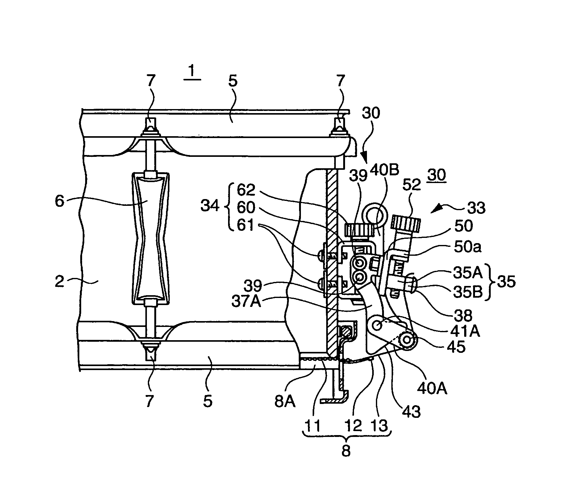
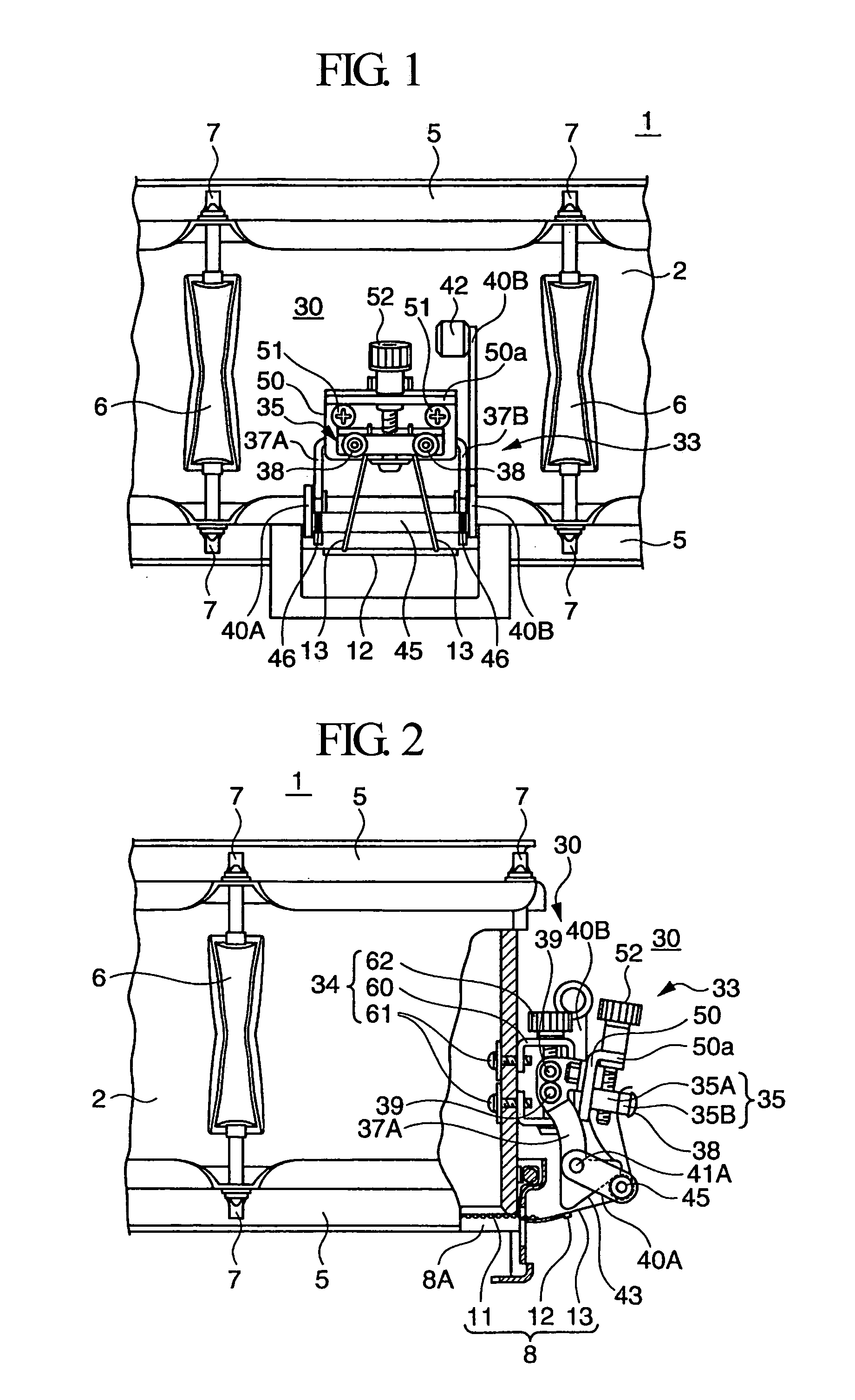
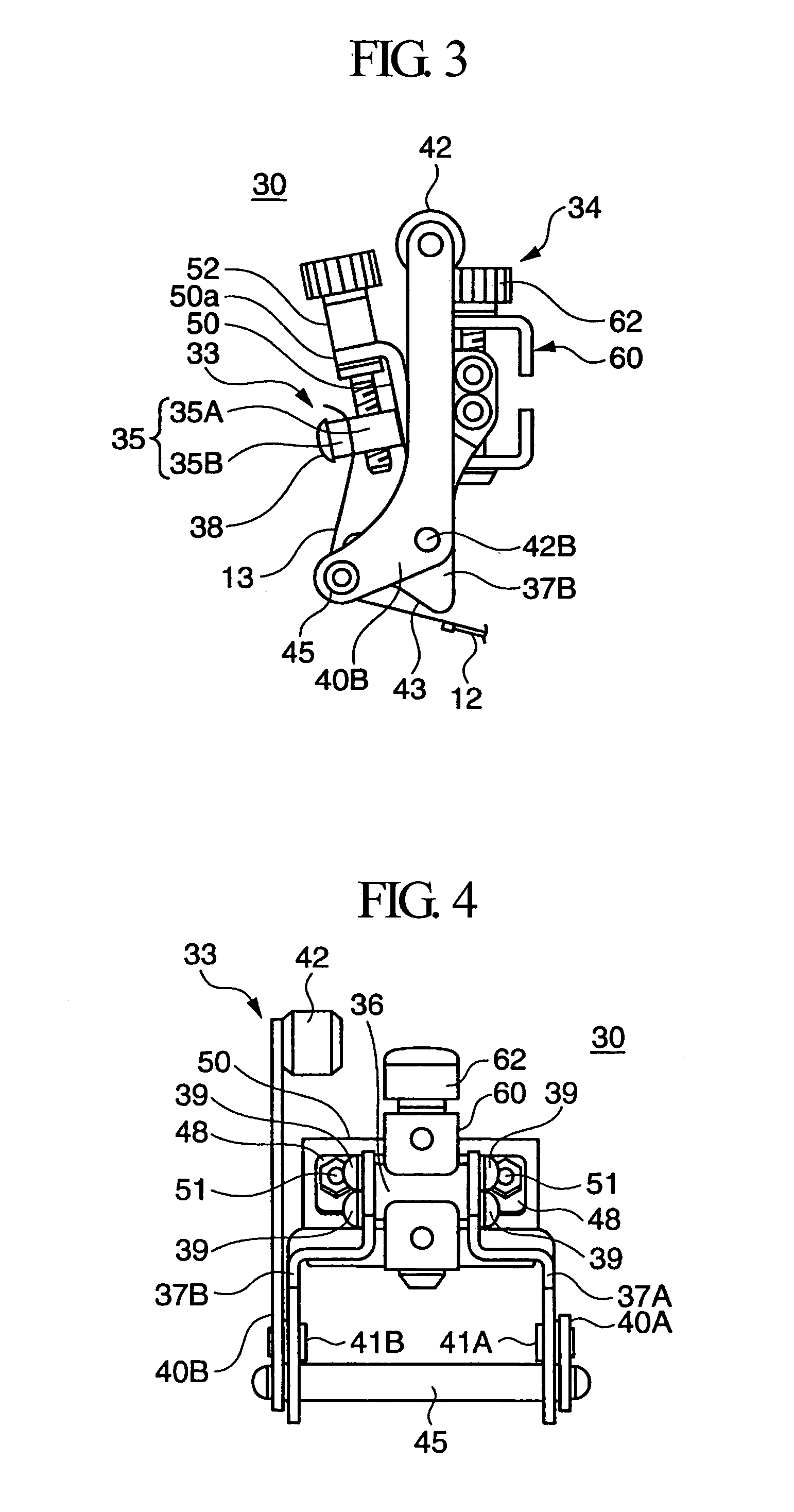
[0036]FIG. 1 is a front view showing a first strainer that is placed in an ON state allowing a snare assembly to move in close contact with a bottom-side drumhead of a snare drum; FIG. 2 is a side view partly in cross section showing the first strainer in the ON state; FIG. 3 is an enlarged side view of the first strainer in the ON state, which is viewed from the right side in FIG. 1; FIG. 4 is an enlarged rear view of the first strainer in the ON state; FIG. 5 is an enlarged view showing essential parts of the first strainer in the ON state; FIG. 6 is a side vi...


PUM


Abstract

A snare strainer includes first and second strainers for respectively holding both ends of a snare assembly (i.e., snares), which is controlled to move in close contact with or apart from a bottom-side drumhead of a snare drum. The first strainer includes a fixed base and a snare stretching member, which further includes a holding member for holding a snare connection member, an interconnection member, a pair of arms attached to both ends of the interconnection member, a pair of levers respectively attached to the arms, and a stretching rod that is bridged between the levers to support the intermediate portion of the snare connection member. The first strainer further includes a tension adjuster for adjusting the tension of the snare connection member, and a height adjuster for adjusting the height of the stretching rod.

Description

BACKGROUND OF THE INVENTION[0001]1. Field of the Invention[0002]This invention relates to snare strainers that control snare assemblies (including snares) to move in close contact with or apart from drumheads.[0003]This application claims priority on Japanese Patent Application No. 2004-37957, the content of which is incorporated herein by reference.[0004]2. Description of the Related Art[0005]Snare drums produce special sound effects called tumbling effects, wherein snare assemblies each corresponding to a plurality of fine snares are controlled to move in close contact with or apart from bottom-side drumheads (corresponding to non-striking sides of snare drums), or they are controlled to move in close contact with or apart from both of bottom-side drumheads and top-side drumheads (corresponding to striking sides of snare drums), so that vibrations of drumheads are transmitted to snares to produce pattering or rattling sounds having light tone colors. The following documents teach ...

Claims


Application Information

Patent Timeline
Patent Type & Authority Patents(United States)
IPC IPC(8): G10D13/02G10D13/00
CPCG10D13/025G10D13/02G10D13/18
Inventor OKAMOTO, SHIGEHIRO
Owner YAMAHA CORP
Why Eureka
Try Eureka