Radiographic equipment

a technology of radiographic equipment and equipment, applied in the direction of material analysis using wave/particle radiation, instruments, greenhouse gas reduction, etc., can solve the problems of limited technique, inability to detect benign organic materials, and low discrimination power of x-rays, so as to enhance the capability of single energy transmission technique, improve the accuracy of information obtained, and minimise scattering

Inactive Publication Date: 2007-12-25
COMMONWEALTH SCI & IND RES ORG
View PDF58 Cites 22 Cited by
  • Summary
  • Abstract
  • Description
  • Claims
  • Application Information

AI Technical Summary

Benefits of technology

[0023]An advantage of the present invention is that the neutrons are essentially mono-energetic. Hence it is possible to model the neutron transmission using a simple exponential relation and moreover, information is more accurately obtained which is useful for material identification.
[0024]The equipment according to at least one embodiment of the invention has the added advantage of direct measurement of transmitted neutrons and is therefore much more efficient when compared with prior art systems which measure secondary radiation such as neutron-induced gamma rays.
[0025]The radiographic equipment may utilise one or more neutron energies. In an example of a dual neutron energy technique, the radiographic equipment may utilise two tubes, one to produce substantially 14 MeV neutrons via the deuterium-tritium fusion reaction and a second to produce substantially 2.45 MeV neutrons via the deuterium-deuterium fusion reaction. The measurement of the neutron transmission at a second energy can be used to enhance the capability of the single energy transmission technique.
[0026]The source of X-rays or gamma-rays may comprise a radioisotope source such as 60Co or 137Cs with energy sufficient to substantially penetrate through the object to be imaged. The 60Co or 137CS source may have an energy of about 1 MeV although other energies may be used depending on the source. Alternatively an X-ray tube, or an electron linear accelerator to produce Bremsstahlung radiation could be used.
[0027]Collimation of both the source of X-rays or gamma-rays and the source of neutrons, advantageously acts to minimise scattering. Furthermore, appropriate collimation of both the sources and detector ensures a narrow beam geometry and therefore greater accuracy when determining the attenuation of neutrons and gamma rays through an object. Moreover, the highly collimated fan-shaped beam provides increased radiation safety. The collimating block may be manufactured from thick paraffin, thick concrete, iron-shot concrete shielding blocks, steel, lead, or the like. Similarly, the or each detector array may be housed within a detector shielding having a slot in order to provide the collimation. The detector collimation shielding may be made from iron and may have a thickness of greater than about 100 mm. The width of the slot may be selected to allow direct passage of neutrons and gamma rays from the source to the detector and to shield the detector array from scattered radiation. The detector slot may be about the same width as the detector array. The source collimator slots may be narrower.
[0028]The detector array may comprise one or more columns of scintillator pixels.

Problems solved by technology

However, X-rays provide little discriminating power between organic and inorganic elements.
Using X-rays the separation of illicit organic materials such as explosives or narcotics from commonly found, benign organic materials is not possible.
In practice the technique is limited by the very expensive and complex particle accelerator, the limited neutron source strength and low gamma-ray detection efficiency and the resulting slow scan speeds.
However it is limited by the very expensive and complex particle accelerator.
However this technique has not been used for imaging and its practical application to contraband detection has not been investigated.
Mikerov found that applications were limited by both the low detection efficiency of the 2 mm thick luminescent screen for fast neutrons and the high sensitivity of the screen to X rays produced by the neutron generator.
However the fact that the fast neutrons are slowed down (thermalised) prior to performing radiography limits the size of the object being imaged to a few cm.
No fast neutron radiography systems are commercially available that involve fast neutron detection.
The key drawbacks of these systems have been their reliance on complex, energy-discriminating neutron detectors and / or their use of sophisticated, high-energy accelerator-based neutron sources.
The main drawback of this scheme is the low contrast between different elements, even when very high energy X-ray sources are used.
The cost of the Perion detector array would also be very high.
The main disadvantage of this method is the low energy of neutrons produced via (gamma, n) reactions.
This limits the ability of the neutrons to penetrate through thick cargoes and increases the difficulty in adequately detecting the transmitted neutrons.
In particular, it is unlikely that the disclosed stacked scintillator detector would be able to distinguish neutrons in the presence of a much more intense X-ray beam.
A disadvantage of both the dual energy X-ray and the X-ray / neutron schemes is that the X-rays and neutrons cover a wide range of energies.
This means that it is not possible to model transmission using a simple exponential relation and that it is not straightforward to extract quantitative cross-section information that could be used for material identification.

Method used


Image

  • Radiographic equipment
  • Radiographic equipment
  • Radiographic equipment

Examples


second embodiment

[0108]A second embodiment applies directly to the dual energy fast neutron transmission embodiment for 14 MeV and 2.45 MeV. However the following discussion also applies to the dual energy transmission at different energies to 2.45 and 14 MeV. However unlike single energy neutron transmission discussed previously, three count rates are measured at each pixel rather than two in the case of single neutron transmission, and two-cross-section ratios can be calculated.

[0109]Suppose that the count rates in a particular pixel from each image are r14, r2,45 and rx respectively. These rates are related to the (unknown) mass of material m between the source and detection points and the (unknown) mass attenuation coefficients of this material for 14 MeV neutrons, 2.45 MeV neutrons and X- or gamma-rays, written as μ14, μ2.45 and μX respectively, by the relations:

r14=R14exp(−mμ14)  (4)

rX=RXexp(−mμX)  (5)

r2.45=R2.45exp(−mμ2.45)  (6)

[0110]where R14, R2.45 and RX are respectively the count rates fo...

embodiment 100

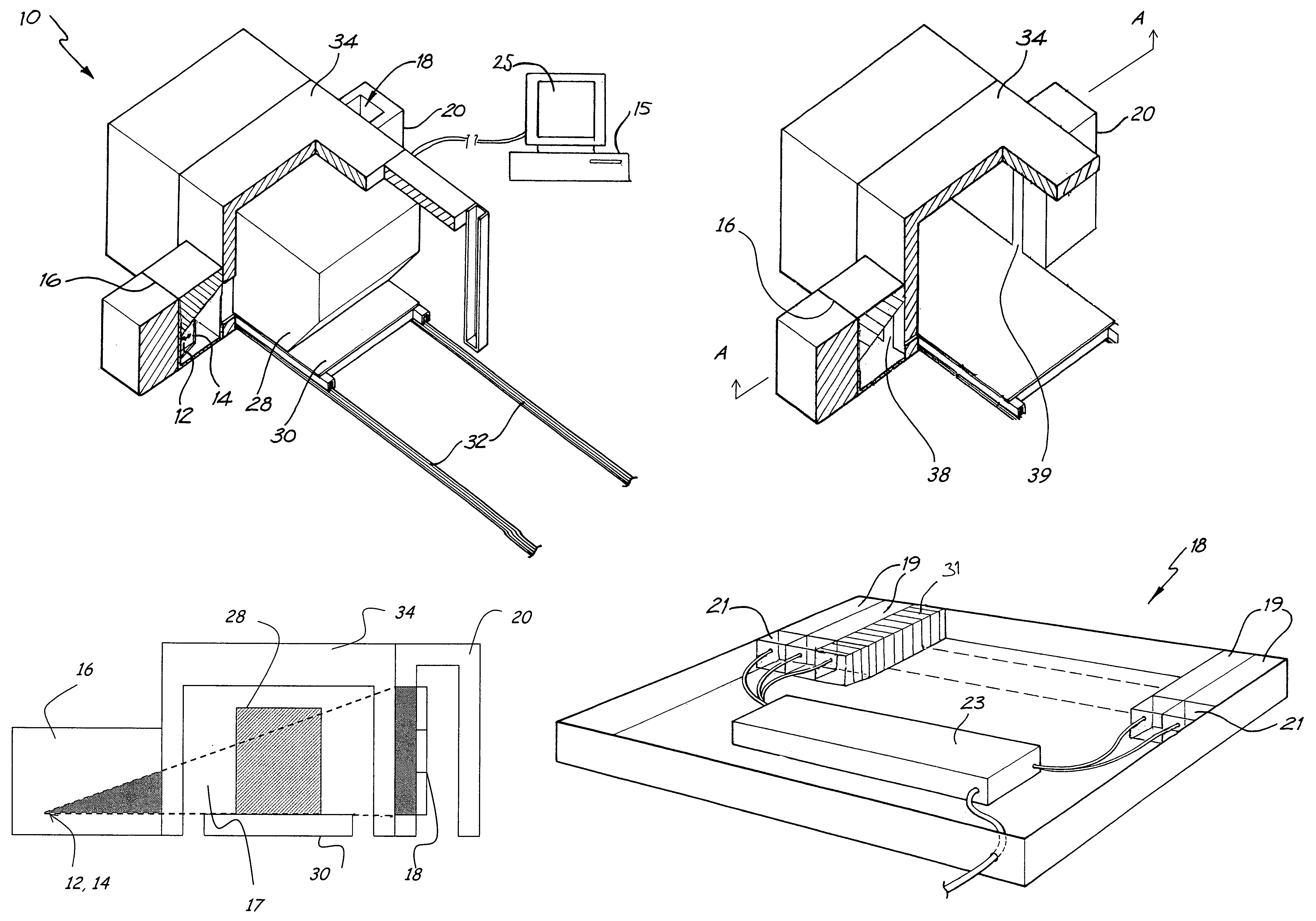
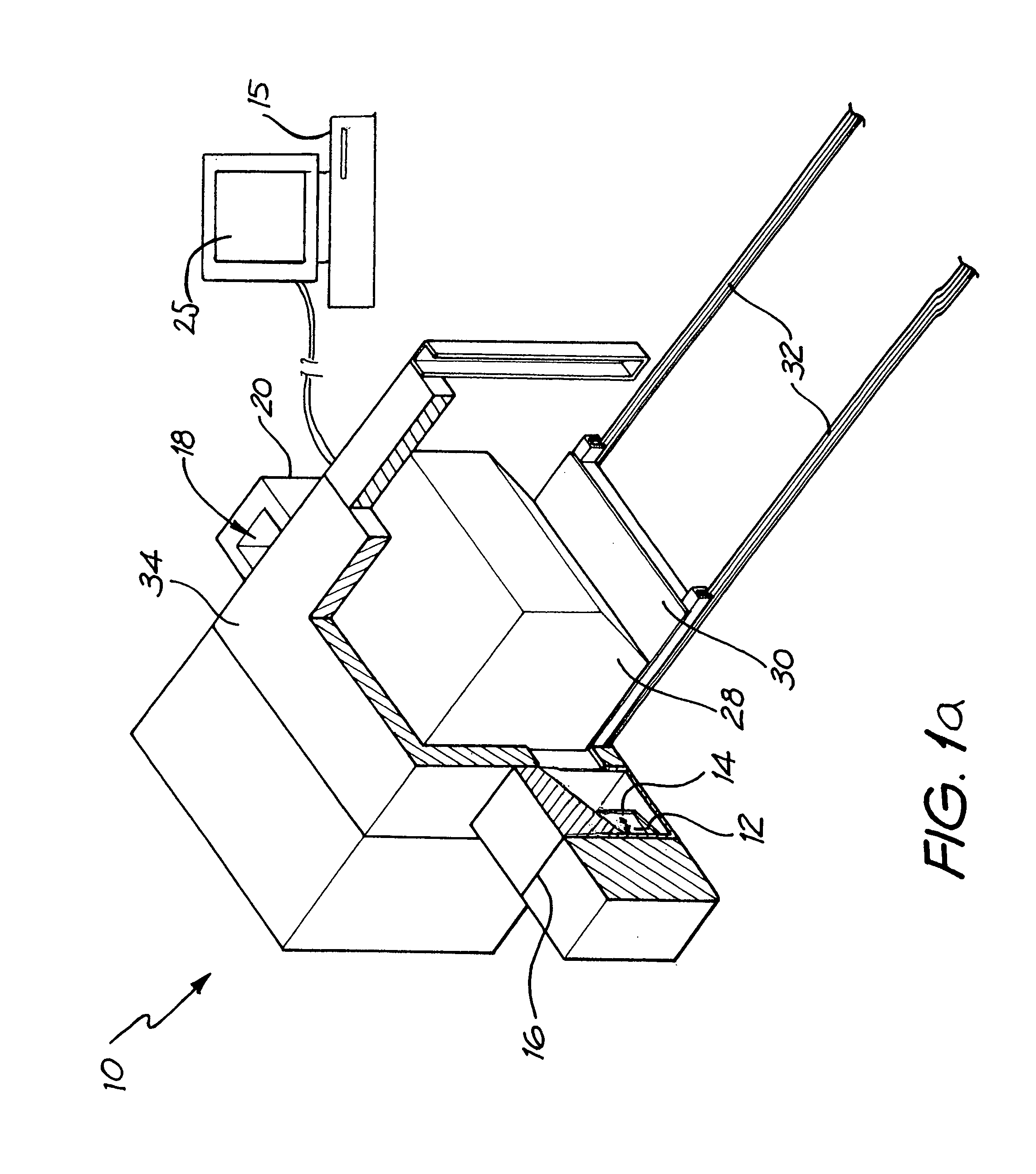
[0124]In the variation (dual neutron energy embodiment 100) as illustrated in FIG. 14, the radiation source comprises three separate generators of radiation, one producing 14 MeV neutrons 112, one producing 2.45 MeV neutrons 113, and the last producing high-energy X- or gamma-ray radiations 114. The neutron sources are sealed tube neutron generators or other compact sources of a similar nature, producing neutrons via D-T and D-D fusion reactions.

[0125]The three radiation sources are operated sequentially as the object is scanned through the analyser. In a first variation, the object is scanned through the analyser three times, with one source being operated for each scan. In a second variation, each source has a separate associated detector (desianated generally as 118) and the object is scanned only once. In a third variation, two or more of the radiation sources are operated at the same time with a single detector, and energy discrimination is used to distinguish the signals from ...


PUM

PropertyMeasurementUnit
energyaaaaaaaaaa
energyaaaaaaaaaa
energyaaaaaaaaaa

Abstract

The invention concerns radiographic equipment. The equipment includes a source of substantially mono-energetic fast neutrons produced via the deuterium-tritium or deuterium-deuterium fusion reactions, comprising a sealed-tube or similar generator for producing the neutrons. The equipment further includes a source of X-rays or gamma-rays of sufficient energy to substantially penetrate an object to be imaged and a collimating block surrounding the neutron and gamma-ray sources, apart from the provision of one or more slots emitting substantially fan-shaped radiation beams. Further included is a detector array comprising a multiplicity of individual scintillator pixels to receive radiation energy from the sources and convert the received energy into light pulses, the detector array aligned with the fan-shaped beams emitted from the source collimator and collimated to substantially prevent radiation other than that directly transmitted from the sources reaching the array. Conversion means are included for converting the light pulses produced in the scintillators into electrical signals. Conveying means are included for conveying an object between the sources and the detector array. Computing means are included for determining from the electrical signals the attenuation of the neutrons and the X-ray or gamma-ray beams and to generate output representing the mass distribution and composition of the object interposed between the source and detector array. The equipment further includes a display means for displaying images based on the mass distribution and the composition of the object being scanned.

Description

[0001]This application is a 371 of PCT / AU2003 / 001641, filed Dec. 10, 2003; the disclosure of which is incorporated herein by reference.TECHNICAL FIELD[0002]This invention concerns radiographic equipment. In particular the invention concerns radiographic equipment for the detection of concealed articles, substances and materials. For instance, the invention may be applied to the detection of concealed weapons, explosives, contraband, drugs and other articles, substances and materials in items such as aircraft baggage, airfreight or shipping containers.BACKGROUND ART[0003]Technologies based on X-rays, gamma-rays and neutrons have been proposed to tackle this problem (Hussein, E., 1992, Gozani, T., 1997, An, J. et al, 2003). The most widely adopted technology is the X-ray scanner which forms an image of an item being examined by measuring the transmission of X-rays through the item from a source to a spatially segmented detector. X-rays are most strongly attenuated by dense, higher ato...

Claims


Application Information

Patent Timeline
Patent Type & Authority Patents(United States)
IPC IPC(8): G01N23/04G01V5/14G01N23/09
CPCG01N23/09G01N23/10Y02E30/10G01T1/16G01V5/00G01T3/00
Inventor SOWERBY, BRIAN DAVIDTICKNER, JAMES RICHARD
Owner COMMONWEALTH SCI & IND RES ORG
Why Eureka
Try Eureka