Camshaft arrangements for engines

Active Publication Date: 2008-01-01
RENAULT SAS
View PDF12 Cites 16 Cited by
  • Summary
  • Abstract
  • Description
  • Claims
  • Application Information

AI Technical Summary

Benefits of technology

[0009]It is an object of the present invention to pr

Problems solved by technology

When the need arises to provide a camshaft sensor target on a portion of a camshaft that is not solid, particular problems may arise in relation to distortion of the target and/or the camshaft, with subsequent adverse effects on the associated part of the tolerance stack.
If a target arrangement for camshaft rotational speed and position sensing is to be provided on a portion of a camshaft that is not solid, it may prove difficult to hold it in position with a sufficient level of accuracy.
For example, with a hollow portion of a camshaft, staking in place a pre-formed target by crimping it to the hollow portion may result in crush deformation of the target, the shaft or both.
That in turn may cause variations in sensor-to-target air-gap tolerance that are unacceptable.
Similar prob

Method used


Image

  • Camshaft arrangements for engines
  • Camshaft arrangements for engines
  • Camshaft arrangements for engines

Examples


Example

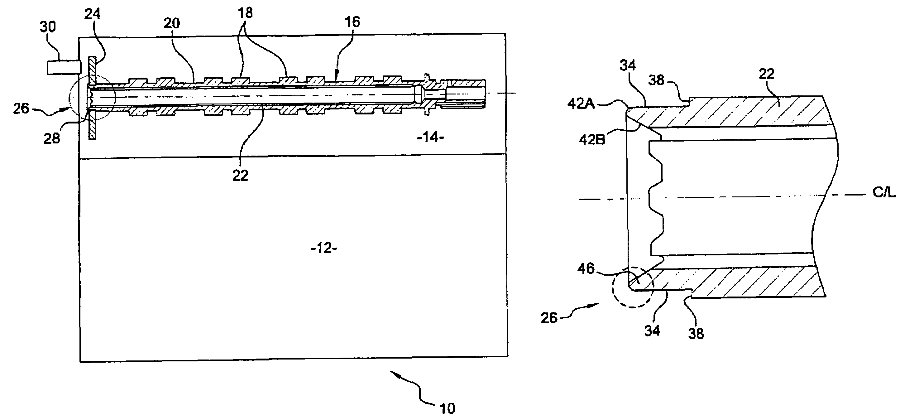
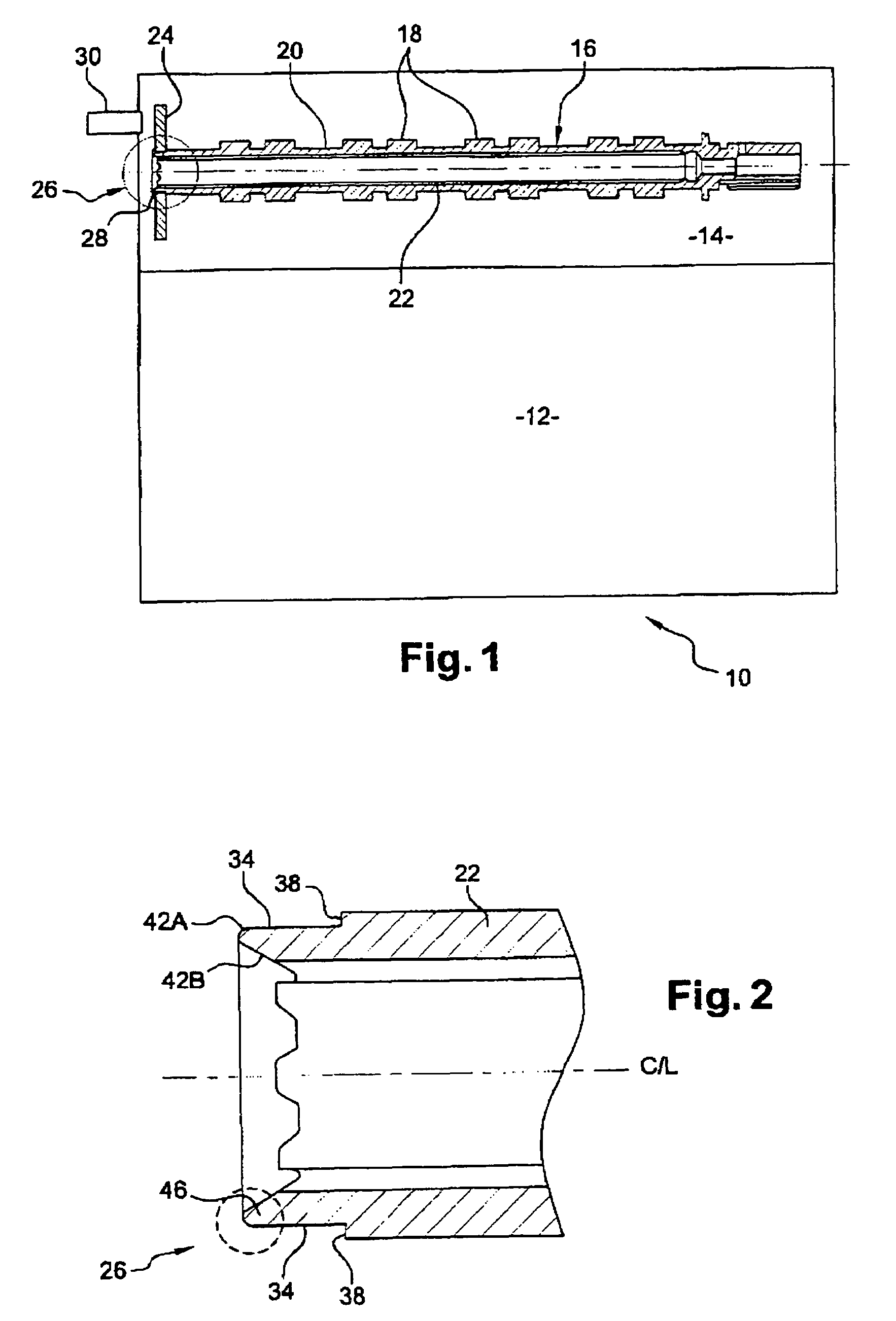
[0029]Referring to the drawings, an engine 10 includes a cylinder block 12 on which is mounted a cylinder head 14. An overhead camshaft assembly 16 runs in the cylinder head 14. The camshaft 16 is a tubular camshaft and is built up from a series of camshaft elements that include a series of camshaft lobes 18 and bearing journals 20, each of which is interlocked onto a tubular support shaft 22.

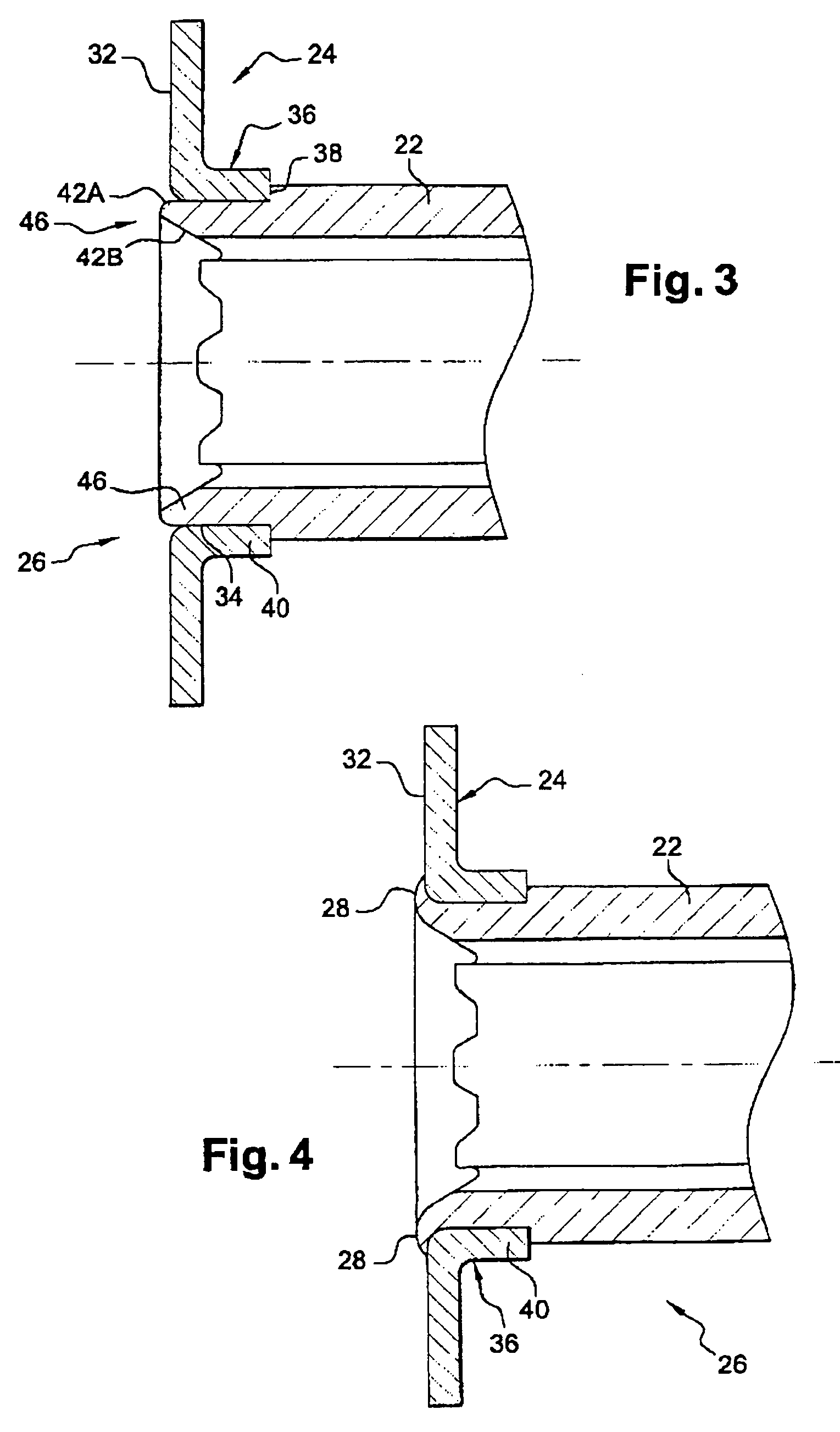
[0030]The camshaft 16 carries a further camshaft element in the form of a rotation sensor target member 24 that is mounted onto one end 26 of the camshaft 16. The target member 24 is fixed onto the camshaft 16 by a rivet head 28 formed from plastic deformation of the support shaft 22 itself, the support shaft 22 acting as the shank of the rivet 22, 28 thus formed. The technique for formation of the rivet head 28 will be described in greater detail below. The rivet head 28 keeps the target member 24 in place on the support shaft 22, at least from the point of view of axial location and preferabl...


PUM

PropertyMeasurementUnit
Deformation enthalpyaaaaaaaaaa

Abstract

A camshaft assembly 16 is disclosed for an engine 10, along with a method of producing the camshaft 16. The camshaft includes a support shaft 22 that carries in the region of one end 26 a camshaft element. The camshaft element may comprise a rotation sensor target member 24 and the support shaft 22 is preferably a tubular shaft. The camshaft element 24 is captured onto the support shaft 22 by deforming a deformation zone 46 at the end of the support shaft 22 into a radially extending rivet head 28.

Description

FIELD OF THE INVENTION[0001]The present invention relates to camshaft arrangements for engines and in particular to a camshaft including a camshaft element mounted thereon for co-rotation therewith. Such a camshaft element may comprise, for example but not exclusively, a target member for a camshaft rotational speed and position sensing arrangement.BACKGROUND OF THE INVENTION[0002]It is known to provide camshafts with targets for rotational speed and position sensors and a prior art example can be found in GB-2317958. In this arrangement, the camshaft sensor target is formed in one piece with the camshaft itself. This requires machining operations to be carried out on the camshaft so as to produce the target lobes from solid.[0003]Instead of forming the sensor target in one piece with the camshaft, in some arrangements a camshaft sensor target is formed as a separate component and is then attached to the camshaft for co-rotation. Examples of such arrangements may be found in U.S. Pa...

Claims


Application Information

Patent Timeline
IPC IPC(8): F01L1/04F01L1/047F01L1/053
CPCF01L1/047F01L1/053Y10T403/4924Y10T29/49293Y10T74/2101
Inventor LE TROADEC, CHRISTOPHEGOURLAY, YVES
Owner RENAULT SAS
Why Eureka
Try Eureka