Subsea pumping module system and installation method

a pumping module and installation method technology, applied in underwater drilling, drilling machines and methods, borehole/well accessories, etc., can solve the problems of increasing operating costs and risks, requiring changes in pab-wct assemblies, and involving equipment and the environment, so as to facilitate the removal of the pumping module and avoid large underwater oil spills.

Active Publication Date: 2008-01-01
PETROLEO BRASILEIRO SA (PETROBRAS)
View PDF16 Cites 49 Cited by
  • Summary
  • Abstract
  • Description
  • Claims
  • Application Information

AI Technical Summary

Benefits of technology

[0017]The configuration of a pumping module installed in a hollow pile (which is the preferred embodiment of the present invention) driven into the seabed especially for this purpose, differs from the current state of art whereby a distinguishing feature of the present invention is that the sole purpose of said hollow pile is to support and hold the vertical pumping module, and is not part of the oil flow system. Said hollow pile may be installed by conventional methods such as drilling or blasting, or by torpedo pile (Brazilian Patent Application PI0106461), whereby said pile is raised a certain distance above the seabed then dropped so that it is driven into the bed by the force of the free fall. The oil flow passes through the pumping module, which is hydraulically linked to the producing well. Moreover, the present invention is constructed so that a pig (line-clearing device) can be passed through the flow lines. The pumping module is coupled to the base structure through a connector-mandrel assembly, with metal-metal sealing. Another advantage is the ease of removing the pumping module, using a vessel with a cable, with no need to disconnect the oil flow lines or any other component, thereby reducing the risk of an underwater oil spill. Such a system is described in the text and claims of the present application.
[0034]In accordance with the present invention, this IFI comprises a cylindrical mandrel with at least two holes (cavities) for oil flow. One hole is interlinked with pump suction flow and the other with pump discharge flow. To render removal of the pumping module easier without causing an oil spill, two on-off valves are installed next to these mandrel holes. By shutting off these valves, suction and discharge flow can be hydraulically isolated, allowing for the pumping module to be installed or removed by cable with no risk of large underwater oil spills. A bypass valve is also installed for rerouting the flow from the pumping module, allowing production to continue whether or not the pumping module is installed and operating.

Problems solved by technology

Once the ESP, production column and wet Christmas tree have been installed at the well, maintenance performed on the ESP increases operating costs and risks, involving the equipment as well as the environment.
Removal of an ESP from the subsea well requires an interruption (loss) of oil production for several days, along with the use of additional equipment and vessels equipped with a rig so that the ESP and production column can be removed, resulting in higher production costs.
Such an application has the disadvantage of requiring changes in the PAB-WCT assembly that alter the manufacturing standard by increasing the weight, size and cost of said assembly.
Moreover, when the pumping module is mounted vertically, its upper end extends above the WCT, hampering light activity at these wells due to the need to remove this module to avoid the risk that the completing riser-blow out preventer (BOP) will strike the module during connection for reentry into the well.
Another drawback of this system is that it cannot be easily applied to existing wells owing to the need to change the production adaptor base (PAB), in other words, re-completing the well with removal of the production column is required.
Nevertheless, this solution presents a number of drawbacks: the dummy well is hydraulically linked to the flow from the oil well, and operates under oil pressure.
When the liner of the dummy well corrodes, maintenance becomes difficult because the liner is buried in the seabed and cannot be recovered.
Nor is another lifting method described to maintain production continuity in case the proposed pumping system fails.

Method used


Image

  • Subsea pumping module system and installation method
  • Subsea pumping module system and installation method
  • Subsea pumping module system and installation method

Examples


Embodiment Construction

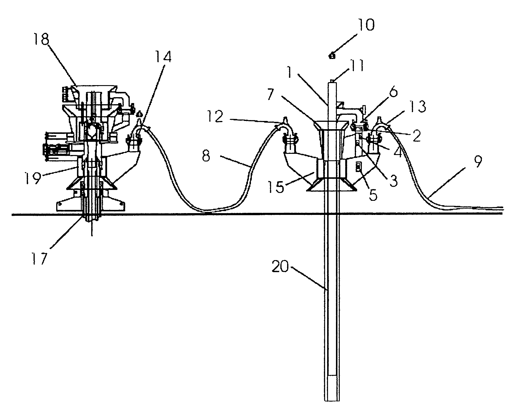
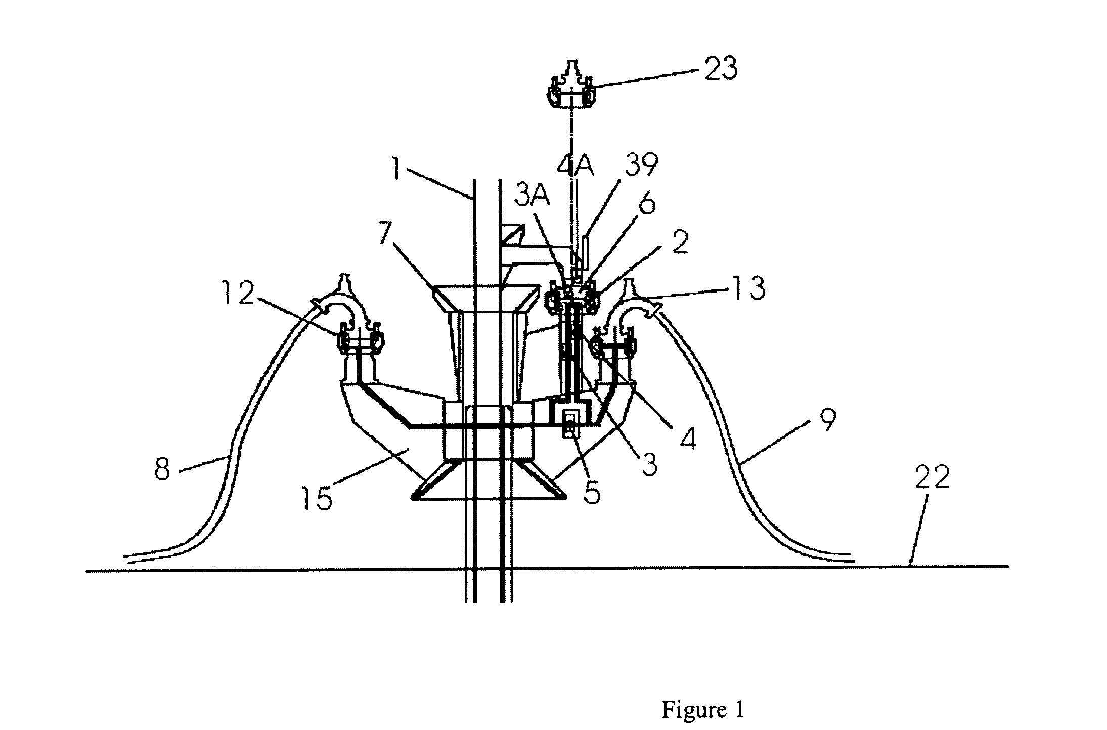
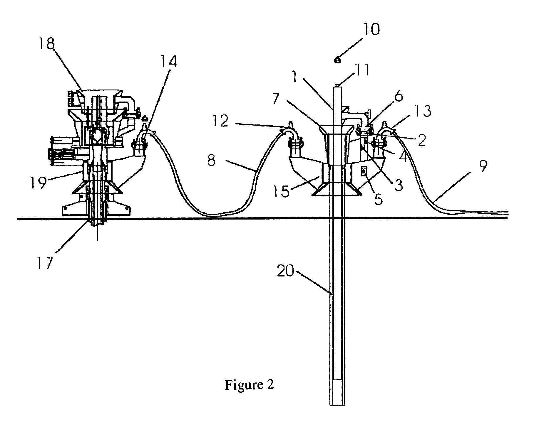
[0051]The following numbers apply to the description of the embodiments of the present invention:[0052]1. pumping module[0053]2. IFI mandrel[0054]3. suction on-off valve[0055]3A. suction on-off valve[0056]4. discharge on-off valve[0057]4A. discharge on-off valve[0058]5. bypass valve[0059]6. pump module connector[0060]7. pumping module guide funnel[0061]8. module upstream flow line[0062]9. module downstream flow line[0063]10. pumping module installation tool[0064]11. pumping module neck[0065]12. VCM—suction[0066]13. VCM—discharge[0067]14. WCT VCM[0068]15. base structure[0069]17. subsea wellhead[0070]18. wet Christmas tree (WCT)[0071]19. production adaptor base (PAB)[0072]20. hollow pile driven into seabed[0073]21. pile[0074]22. seabed[0075]23. closed cover[0076]24. base guide funnel[0077]29. seal protector[0078]30. pump motor[0079]31. pump[0080]32. pumping module flow inlet[0081]33. pumping module flow outlet[0082]34. pump support[0083]35. mechanical synchronizer[0084]36. pump casing...


PUM


Abstract

The present invention contemplates a system comprising a pumping module coupled to an intermediate flow inlet (IFI) wherein said IFI is coupled to a base structure disposed on the flow line that routes production from one or more oil wells, allowing for the quick and easy installation or recovery of a subsea pumping module by cable from an inexpensive vessel. The present invention also allows for the hydraulic isolation of the subsea pumping module by means of on-off valves on the IFI whereby the pumping module can be easily installed or removed without causing underwater oil spills. Sealing of the connection is of the metal-metal type. It is also possible to pass a pig through the present system for clearing the flow lines.

Description

FIELD OF INVENTION[0001]The present invention relates to subsea equipment installed on the seafloor and intended for oil production, and which can also be applied to water injection systems in hydrocarbon reservoirs. More specifically, the present invention relates to pumping modules coupled to an intermediate flow inlet on a subsea base, whereby said modules can be installed as well as recovered by cable. The present invention further relates to the method for installing said pumping module.BACKGROUND OF THE INVENTION[0002]Offshore oil production requires that subsea wells be drilled and that equipment such as Christmas tree manifolds, oil flow lines, gas injection lines and water injection lines be installed between the wellheads and the processing facilities. These processing facilities may be located on a vessel, platform, or even on land.[0003]Christmas tree manifolds are assemblies of connectors and valves installed at the top of an oil wellhead and are used to block (open and...

Claims


Application Information

Patent Timeline
Patent Type & Authority Patents(United States)
IPC IPC(8): E21B29/12E21B33/035E21B33/038E21B43/00E21B43/12
CPCE21B33/038E21B43/128E21B43/121
Inventor RODRIGUES, ROBERTODE MATOS, JOAO SIQUEIRAPEREIRA, CARLOS ALBERTO GIACOMIMFARIAS, JACKSON BURJACKJUNIOR, ROBSON SOARES
Owner PETROLEO BRASILEIRO SA (PETROBRAS)
Why Eureka
Try Eureka