Electric bicycle

a technology of electric bicycles and pedal shafts, applied in the direction of electric propulsion mounting, bicycles, transportation and packaging, etc., can solve the problems of increasing costs, increasing costs, and increasing the cost, and achieve the effect of easing pedaling

Inactive Publication Date: 2008-01-01
SANTA MONICA ELECTRIC VEHICLES
View PDF17 Cites 28 Cited by
  • Summary
  • Abstract
  • Description
  • Claims
  • Application Information

AI Technical Summary

Benefits of technology

[0020]Another conventional bicycle chain is operatively connected around the conventional large sprocket on the pedal shaft and the sprocket on the conventional freewheel, screwed onto the outer case of the motor in the conventional location. This arrangement provides the rider with the ability to drive the motor, and, in turn, the rear wheel by pedaling the bicycle. Since this type of motor offers almost no resistance to rotation when the power is turned off, this bicycle can be pedaled with almost the same ease as a non-electric bicycle with the same rear hub. Fitted with the appropriate circuitry, at the command of the rider, the motor can be pedaled forward to recharge the batteries. This adds only minimally to the effort of pedaling, and it is particularly convenient if the bicycle is on at least a slight downhill grade.
[0033]It can be seen from the description of the prior art and the above summary of the present invention, how this unique, new concept of a simple, multi-speed drive, which is rotated at a speed that creates the least amount of friction loss for both the pedal power up-speed and the motor power reduction, overcomes the efficiency limitations of the prior art. For the first time, a practical, efficient regenerative charging system for an electric bicycle can be accomplished due to this new technology. The present invention also has the advantage of being able to be fitted into an existing bicycle design, just above the pedal shaft, where it does not prevent the battery module from being mounted low (close to the ground) on the frame.

Problems solved by technology

This method is so inefficient that it is almost impractical.
State of the art drives through the pedal shaft to the rear wheel are usually heavy, bulky gearboxes with electric motors attached and a pedal shaft protruding on each side.
There are a few versions that allow the motor to drive the rear wheel without turning the pedals, but they require additional mechanisms, which increase the cost.
A disadvantage of this type of drive is that the pedal shaft turns at about one third of the speed of the rear wheel in high gear; therefore, the rotational speed of the motor must be reduced about three times further when driving through the pedal shaft, than when driving the wheel directly.
Both the additional reduction and the subsequent up-speed add to the friction losses and cause a significant loss in overall efficiency.
Therefore, another disadvantage of driving through the pedal shaft is that the bulky transmission and motor combination around the pedal shaft causes the battery to be relegated to a higher position, away from the center of the bicycle.
Direct drives to the rear wheel take many different forms, but one disadvantage common to all of them is that they require another drive chain and sprocket, or belt and pulley to the rear wheel, in addition to the customary pedal chain and sprocket.
They are made for either front or rear wheel application, but when applied to the front wheel of a bicycle, they create a gyroscopic force that at high speed makes the bicycle hard to steer and dangerous in some conditions.
It is well known by those skilled in the art of designing vehicles that this is a highly undesirable characteristic from a handling and safety point of view.
When applied to the front of a bicycle with front suspension, the large increase in un-sprung weight renders the suspension practically ineffective, and the same is true at the rear.
Therefore, a bicycle with a single gear ratio electric drive is very inefficient when climbing a hill, because it must slow down to develop the required torque to overcome the hill.
In moderately hilly terrain, this inefficiency can cut the range of the bicycle in half.
The steeper the hill, the less efficient the motor becomes.
On a long hill, this wasted energy usually heats up the motor enough to open the thermal protection switch and turn off the power before the bicycle reaches the top of the hill.
Therefore, any of the prior art bicycles that used this type of devices to increase the hill climbing ability of the motor do not have the ability to recharge the battery through the electrical generation capability of the motor while coasting downhill.
In fact, there does not seem to be any evidence that there has ever been a bicycle with more than a single gear ratio electric drive that had the ability to drive the motor while coasting downhill.

Method used


Image

  • Electric bicycle
  • Electric bicycle
  • Electric bicycle

Examples


Embodiment Construction

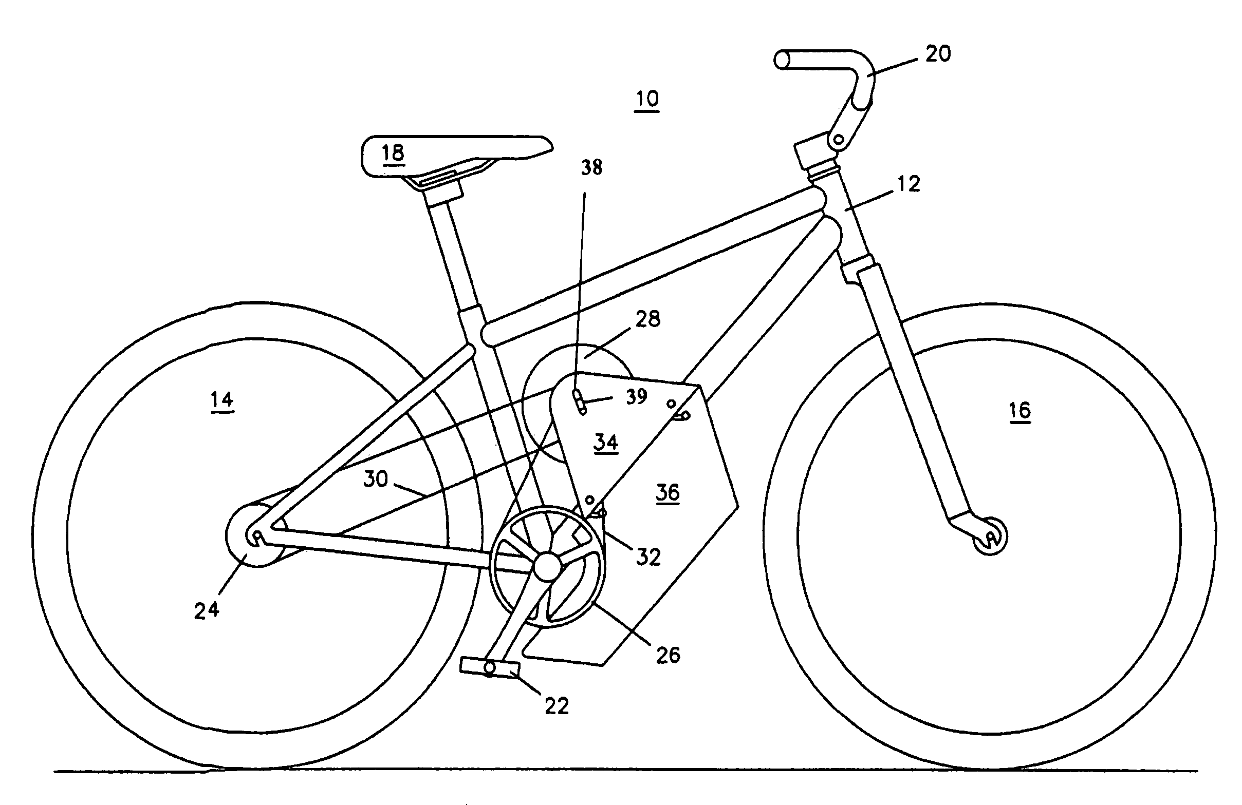
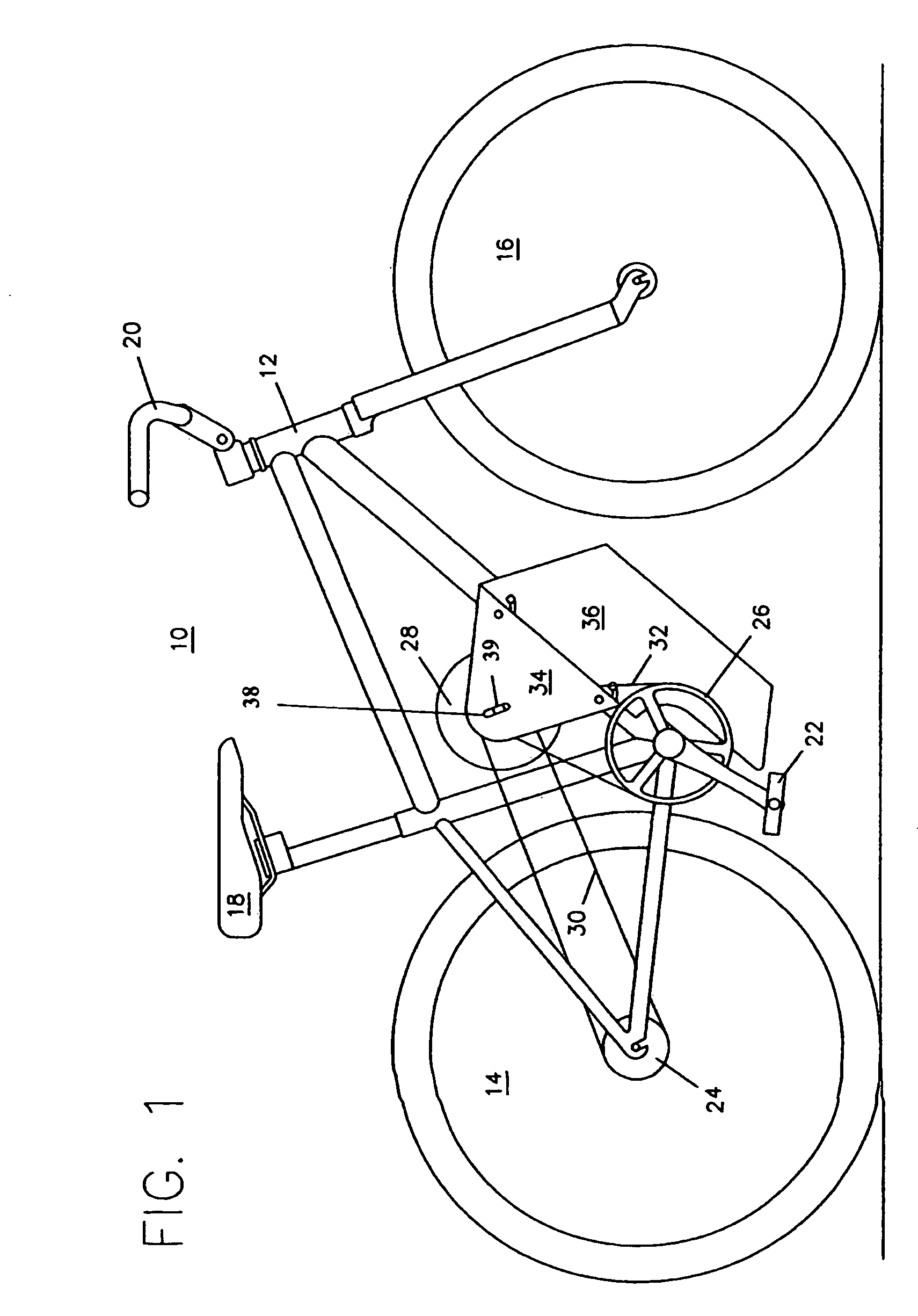
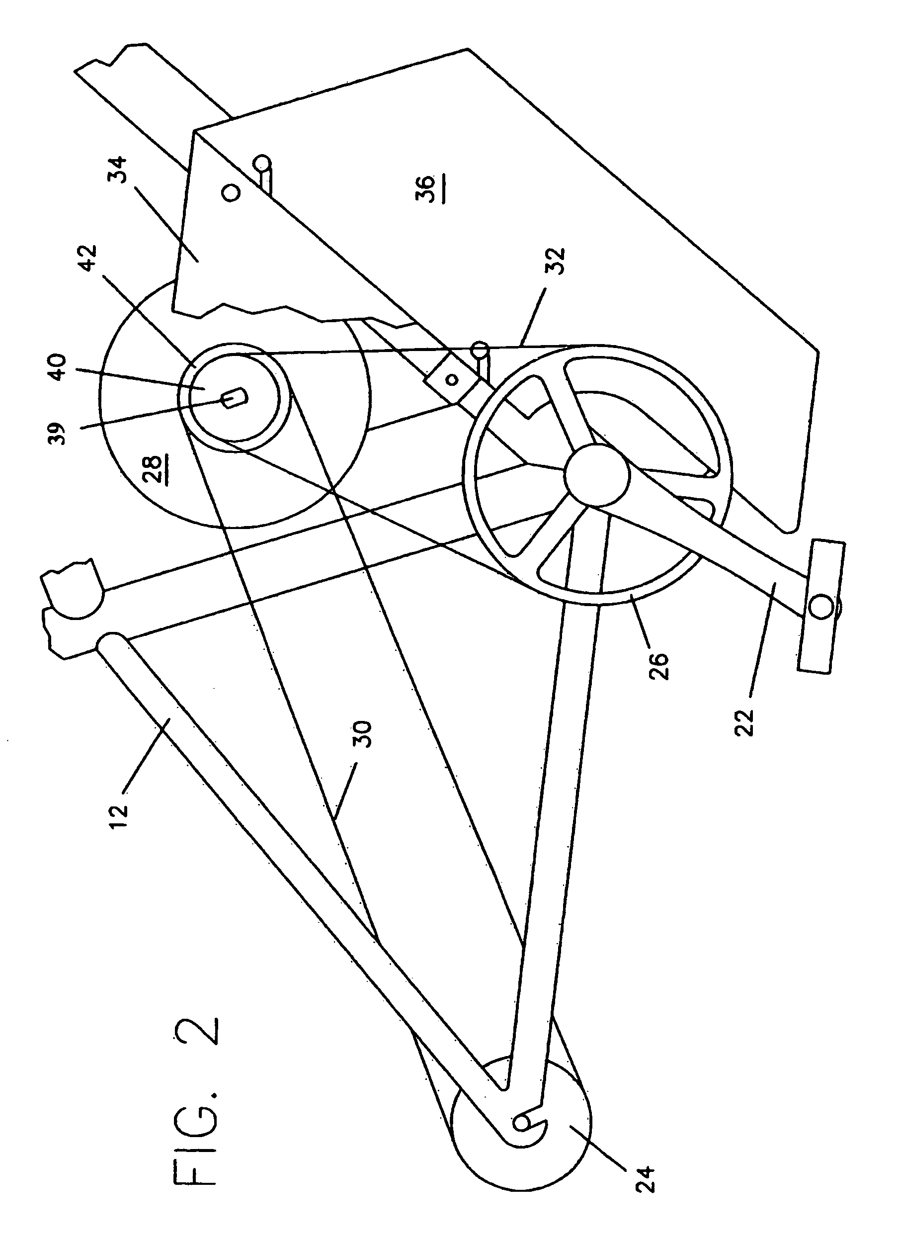
[0041]Referring to FIG. 1, an electric powered bicycle 10 of the present invention preferably includes a frame and fork assembly 12, a front wheel assembly 16, a rear wheel assembly 14, a seat assembly 18, a handle bar assembly 20, a front and rear brake assembly (not shown), a pedal crank assembly 22, a multi-speed rear hub assembly 24, a pedal sprocket 26, a hub motor assembly 28, a hub motor axle 39, a drive chain 30, a pedal chain 32, a motor support bracket 34, and a battery module 36. The battery module 36 is mounted to the frame 12 in a way that makes it easy to remove in the forward direction and easy to replace in the reverse direction. The battery module 36 fits between sprocket 26 and the left side of pedal crank assembly 22 at a position no lower (closer to the ground) than pedal 22 at its lowest position.

[0042]Motor 28 was designed as a bicycle hub motor and, therefore, the outer case turns while the axle 39 remains fixed. Bracket 34 is mounted to frame 12 and supports ...


PUM


Abstract

An electrically powered bicycle includes a hub motor, which is mounted to the bicycle frame by its axle. A drive sprocket mounted to the outer case of motor is engaged by a chain to the sprocket on a multi-speed hub on the rear wheel, so that when the motor turns, it drives the wheel. A freewheel, also mounted to the outer case of motor, is engaged by a chain to the large sprocket on the pedal crank, such that when the motor is operating, it does not turn the pedal sprocket. When the pedals and the motor are both operating and the sprocket on the freewheel is rotated as fast as the motor, the pedals can drive the motor, and consequently, the bicycle. An additional driven sprocket is mounted to the motor case and an additional freewheel is mounted to the multi-speed hub, and both are connected by a third chain so that when the bicycle is coasting (i.e., the motor is not driving the rear wheel), the rear wheel will drive the motor to provide downhill, regenerative braking capability.

Description

FIELD OF INVENTION[0001]The present invention relates in general to electric powered bicycles, and more particularly to new, improved technology for electric powered bicycles that provides, among other things, steeper and more efficient hill climbing ability, longer range, and a smother ride than the prior art, plus downhill regenerative braking.BACKGROUND OF THE INVENTION[0002]Prior art electric drives for bicycles can be divided into the following four basic types:[0003](1) Friction drive on the tire;[0004](2) Drives through the pedal shaft to the rear wheel;[0005](3) Direct drives to the rear wheel; and[0006](4) Wheel hub motors.[0007]The cheapest and simplest type of electric drive for a bicycle is a friction drive on the front or rear tire. This method is so inefficient that it is almost impractical. However this type will probably continue to be built and sold, because they can be easily installed on an existing bicycle as a kit. U.S. Pat. No. 6,065,557 to von Keyserling, U.S....

Claims


Application Information

Patent Timeline
Patent Type & Authority Patents(United States)
IPC IPC(8): B60K1/00B62K11/00B62M23/02B62M6/60B62M6/70B62M6/90
CPCB62M6/60B62M6/70B62M6/90
Inventor HOLLAND, RONALD A.
Owner SANTA MONICA ELECTRIC VEHICLES
Why Eureka
Try Eureka