Integrated two-speed motor

a two-speed motor and shifter technology, applied in the direction of electric propulsion mounting, electric devices, electric devices, etc., can solve the problems of unsuitable addition of gear boxes, and achieve the effect of reducing overall weight and saving packaging spa

Inactive Publication Date: 2008-01-08
ARVINMERITOR TECH
View PDF8 Cites 32 Cited by
  • Summary
  • Abstract
  • Description
  • Claims
  • Application Information

AI Technical Summary

Benefits of technology

[0009]The gear assembly includes a first gear, a second gear, and a plurality of pinion gears that are supported on a spider. The spider is fixed for rotation with an output shaft and each pinion gear is in meshing engagement with the first and second gears. A gear housing is positioned within the inner cavity and substantially surrounds the first gear, second gear, and plurality of pinion gears. The first clutch assembly selectively couples the first gear to the gear housing to provide high-speed output capability and the second clutch assembly selectively couples the second gear to ground, i.e. non-rotating outer housing, to provide low-speed output capability.
[0010]The subject invention provides an electric motor and two-speed shifting mechanism for a vehicle drive that is incorporated within a common housing, which saves packaging space, reduces overall weight, and allows the electric motor and the two-speed shifting mechanism to share a common cooling system.

Problems solved by technology

Additional gear boxes are not desirable because the gear boxes occupy valuable packaging space that is needed for other vehicle components.

Method used


Image

  • Integrated two-speed motor
  • Integrated two-speed motor
  • Integrated two-speed motor

Examples


Embodiment Construction

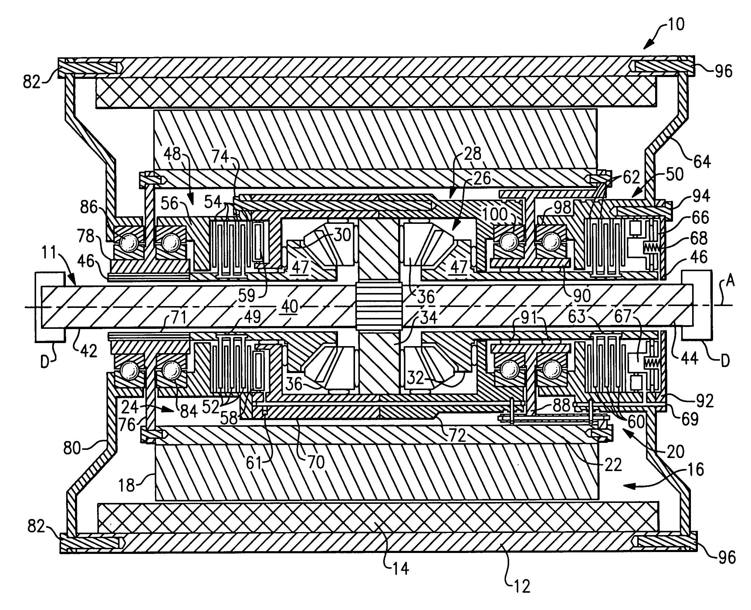
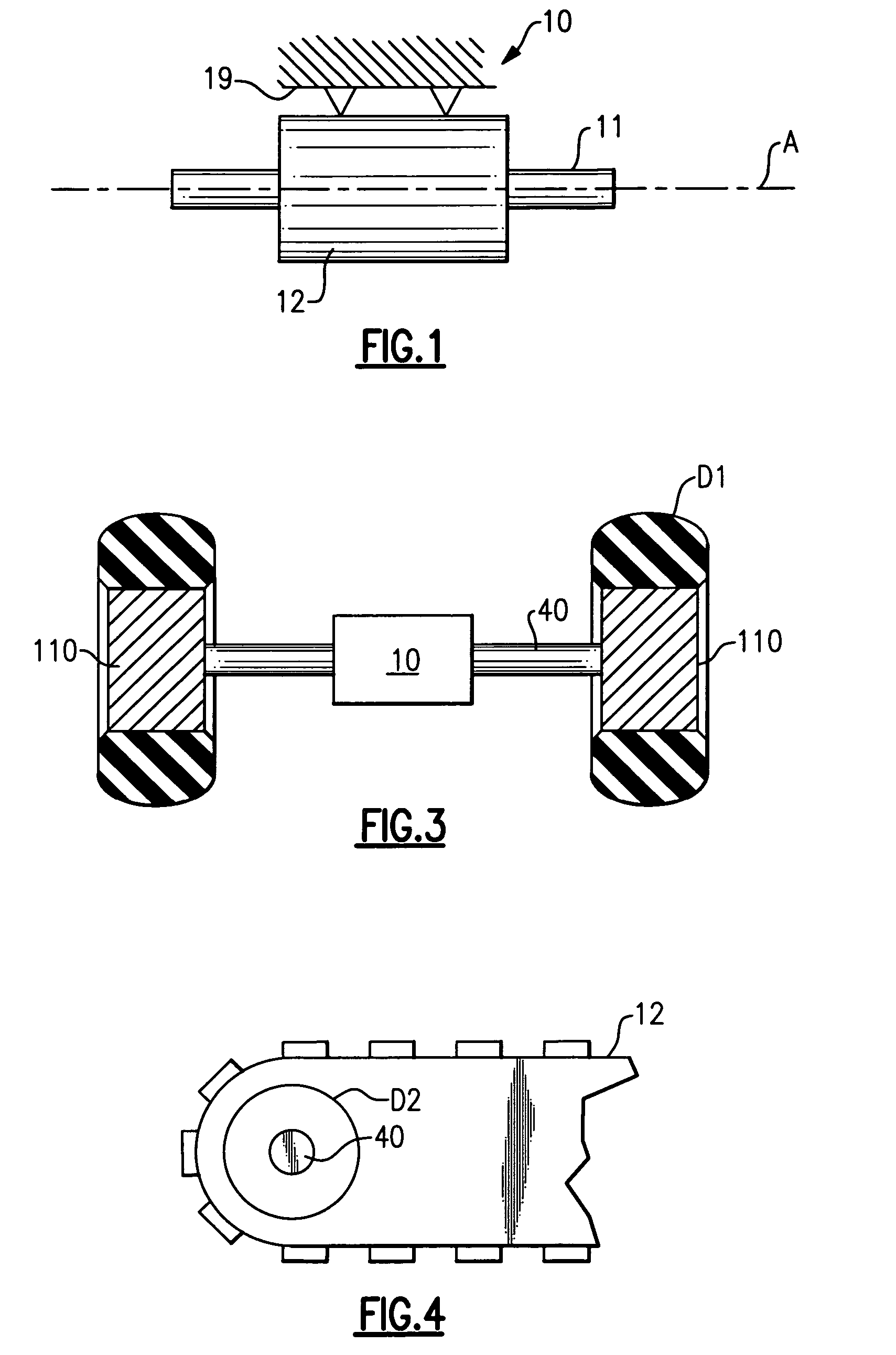
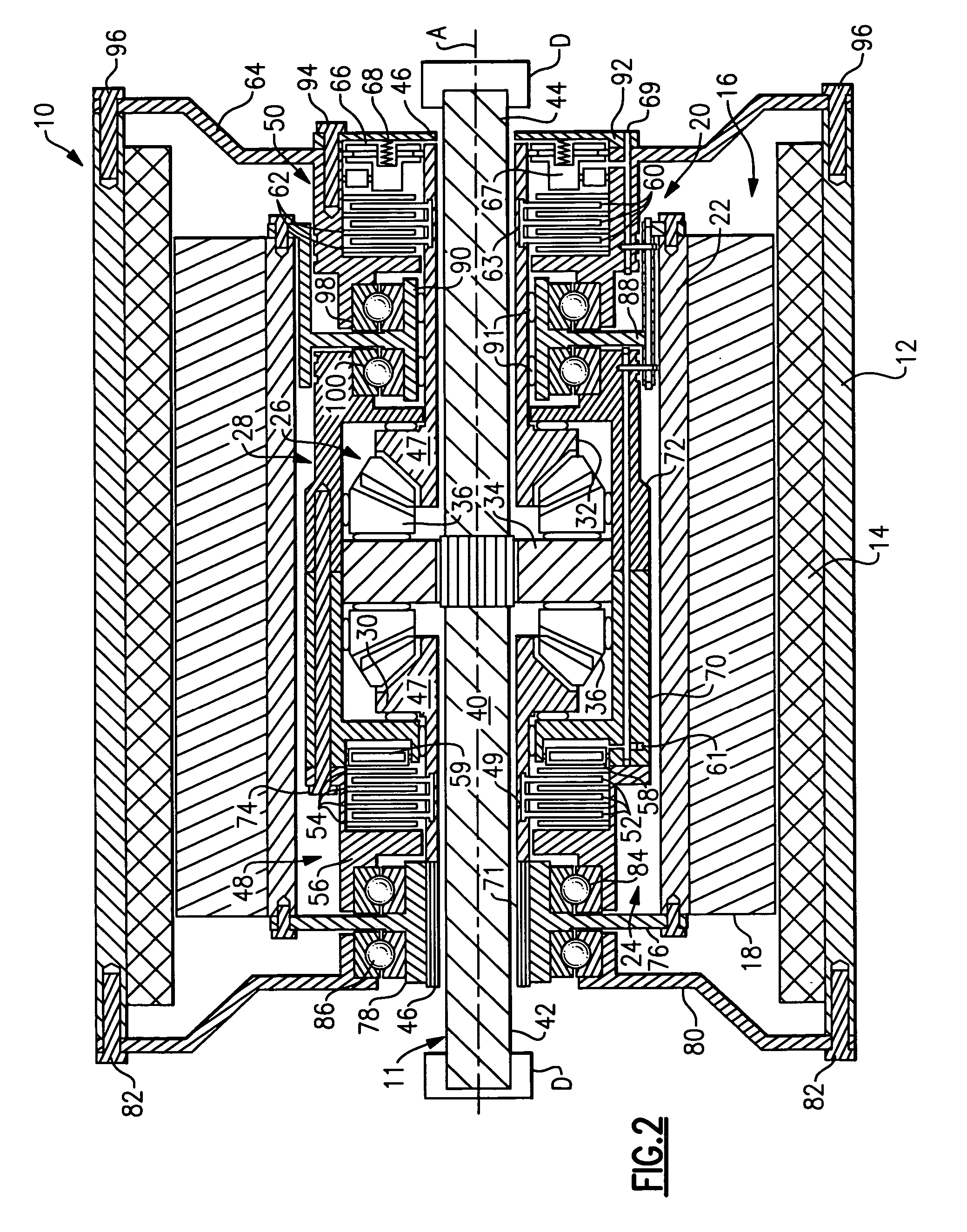
[0016]An electric motor 10, shown in FIG. 1, is used in a vehicle application to drive an output 11. The electric motor 10 includes an outer housing 12 that supports a stator 14 as shown in FIG. 2. The stator 14 defines an inner cavity 16 that receives a rotor 18. The rotor 18 is spaced apart from the stator 14 and is mounted for rotation relative to the stator 14 about an axis A. The stator 14 and outer housing 12 are non-rotating components that are supported by vehicle structures, such as a vehicle frame or chassis 19, for example.

[0017]A two-speed shifting mechanism, shown generally at 20 in FIG. 2, is incorporated into the rotor 18. The rotor 18 is supported on an inner rotor support 22 that defines an inner cavity 24. The two-speed shifting mechanism 20 is positioned within the inner cavity 24. The two-speed shifting mechanism 20 includes a gear assembly 26 positioned within a gear housing 28 formed from multiple housing components. Because the two-speed shifting mechanism 20 ...


PUM


Abstract

A vehicle drive assembly includes an integrated two-speed motor that can selectively drive an output at a high operating speed or a low operating speed. The two-speed motor includes a stator mounted to a non-rotating outer housing, and a rotor that is mounted for rotation relative to the stator. The rotor is supported an inner rotor support that defines an inner cavity. A two-speed shifting mechanism is incorporated into the inner cavity and is used to drive an output. The two-speed shifting mechanism includes a gear assembly and first and second clutch assemblies that cooperate with each other to provide low and high speed output capability as needed.

Description

RELATED APPLICATION[0001]This application claims priority to U.S. Provisional Application No. 60 / 605,094, which was filed on Aug. 27, 2004.TECHNICAL FIELD[0002]This invention generally relates to an electric motor vehicle drive with an integrated two-speed shifter.BACKGROUND OF THE INVENTION[0003]Many hybrid electric applications operate more effectively with a two-speed transmission. This capability is certainly beneficial to hybrid electric applications such as transit buses and military vehicles, which require a wide range of operational speeds. In these applications, electric motors are used to provide driving input to a drive axle or gear box that ultimately drives the vehicle.[0004]In the example of a transit bus, an electric motor can power a drive axle extending between a pair of vehicle wheels. The drive axle typically includes a carrier that houses a differential gear assembly, which allows speed differentiation between laterally opposed wheels as the bus negotiates a turn...

Claims


Application Information

Patent Timeline
Patent Type & Authority Patents(United States)
IPC IPC(8): F16H48/06
CPCB60K17/043F16H3/50H02K7/108B60L3/0061H02K7/116B60K2001/001F16H2200/0034B60L2220/50B60L2200/18B60L2220/44B60L2240/36B60L2240/421Y02T10/64
Inventor BENNETT, JOHN L.
Owner ARVINMERITOR TECH
Why Eureka
Try Eureka