
Tubing running equipment for offshore rig with surface blowout preventer

a technology of surface blowout prevention and tubing running equipment, which is applied in the field of equipment and methods for running tubing or casing with an offshore rig, can solve the problems of large lmrp/bop and bulkyness

Active Publication Date: 2008-01-15
VETCO GRAY LLC
View PDF27 Cites 52 Cited by
  • Summary
  • Abstract
  • Description
  • Claims
  • Application Information

AI Technical Summary

Benefits of technology

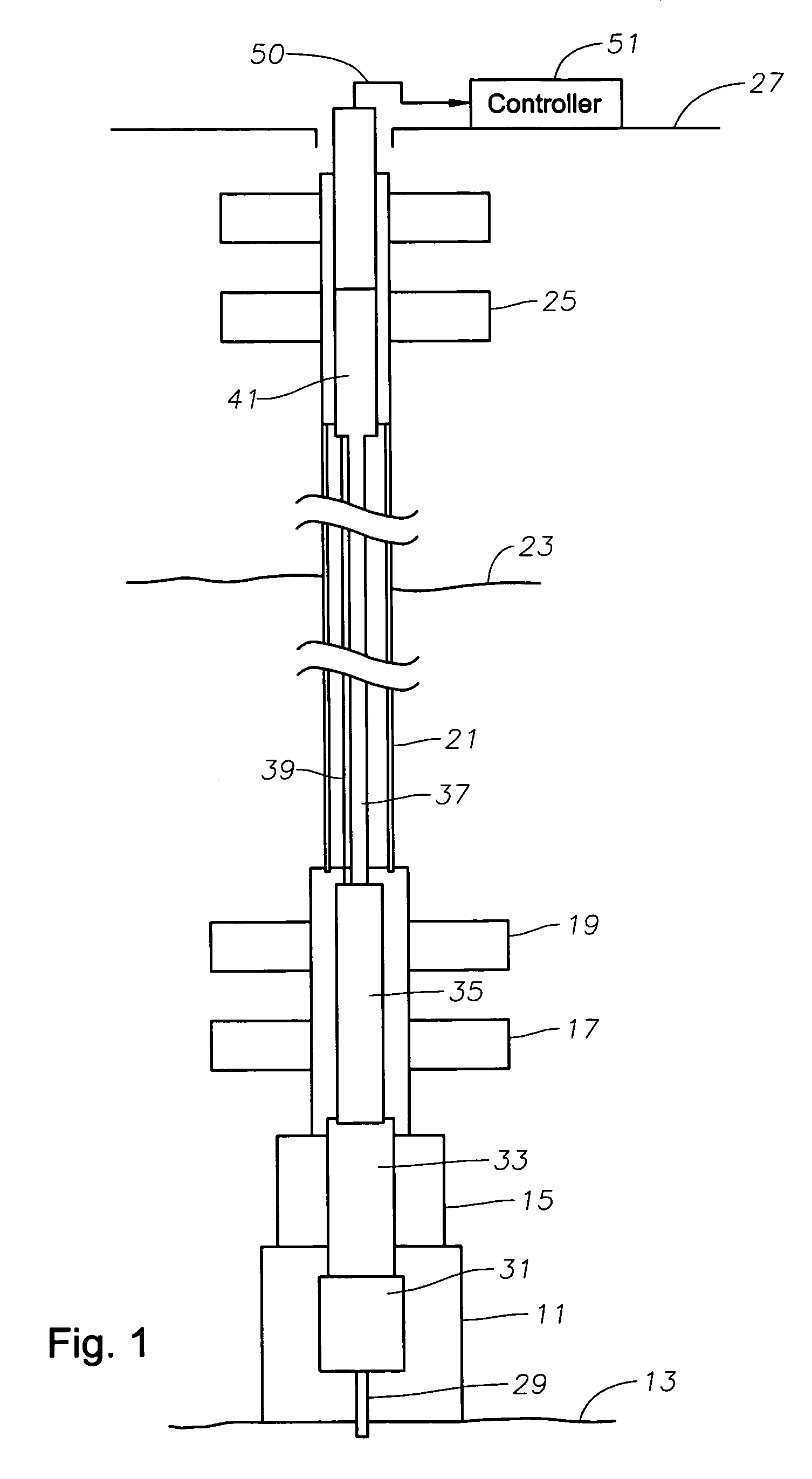
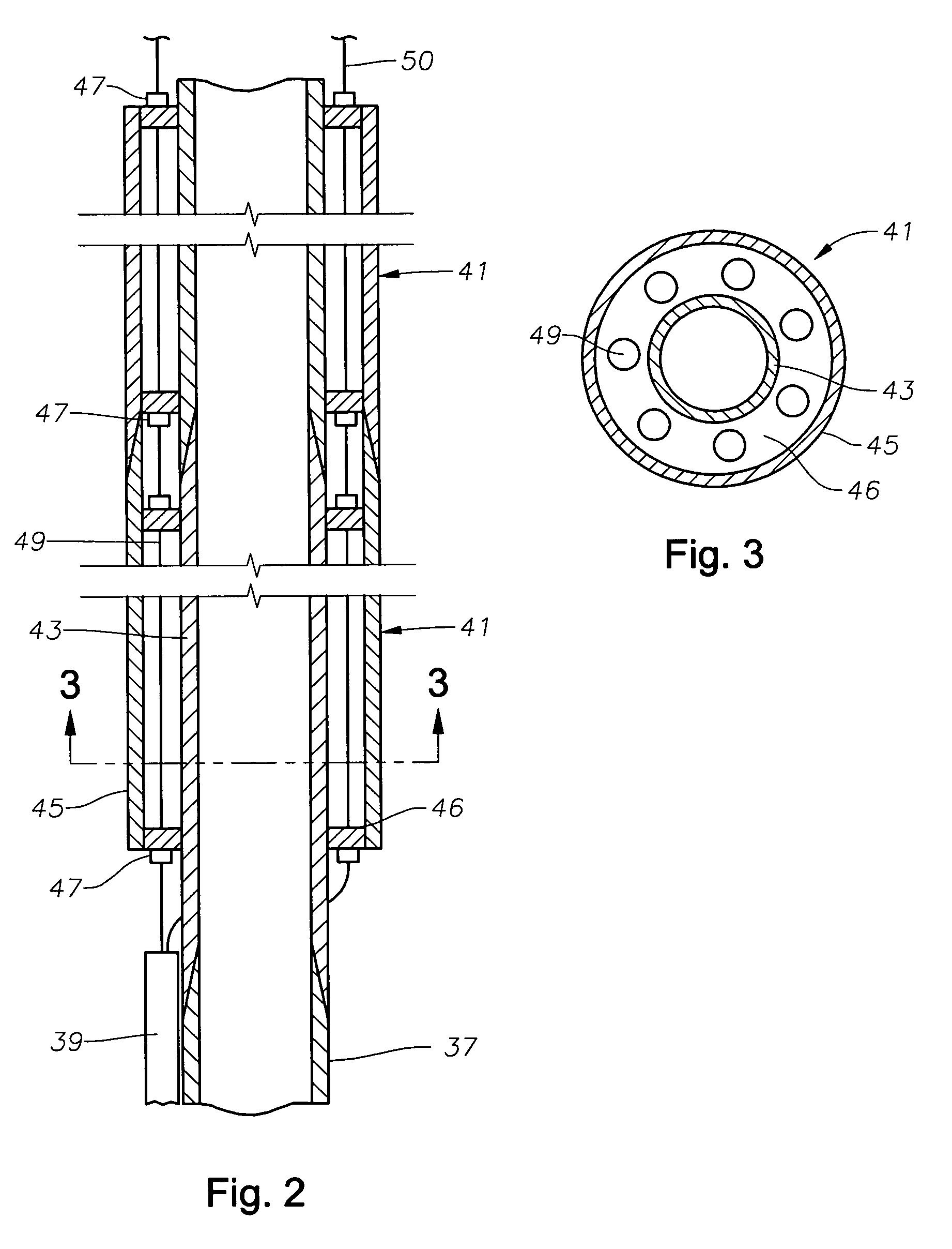
"The patent describes a method for performing operations in a subsea wellhead assembly through a riser extending between the wellhead assembly and a surface platform. The method involves connecting a surface blowout preventer to the riser, connecting a tool to a string of conduit, and connecting a control line to the tool. The tool and control line are then lowered through the blowout preventer and riser. The method can also include mounting a slick joint to the conduit, connecting the control line through the slick joint, and communicating with the tool to perform the operation. The technical effect of this patent is to provide a safe and efficient method for performing subsea wellhead assembly operations."

Problems solved by technology

One of the drawbacks of these arrangements is that the LMRP / BOP is very large and bulky with numerous electrical and hydraulic control lines extending from the surface vessel in order to monitor and operate the subsea LMRP / BOP.

Method used


Image

  • Tubing running equipment for offshore rig with surface blowout preventer
  • Tubing running equipment for offshore rig with surface blowout preventer
  • Tubing running equipment for offshore rig with surface blowout preventer

Examples


second embodiment

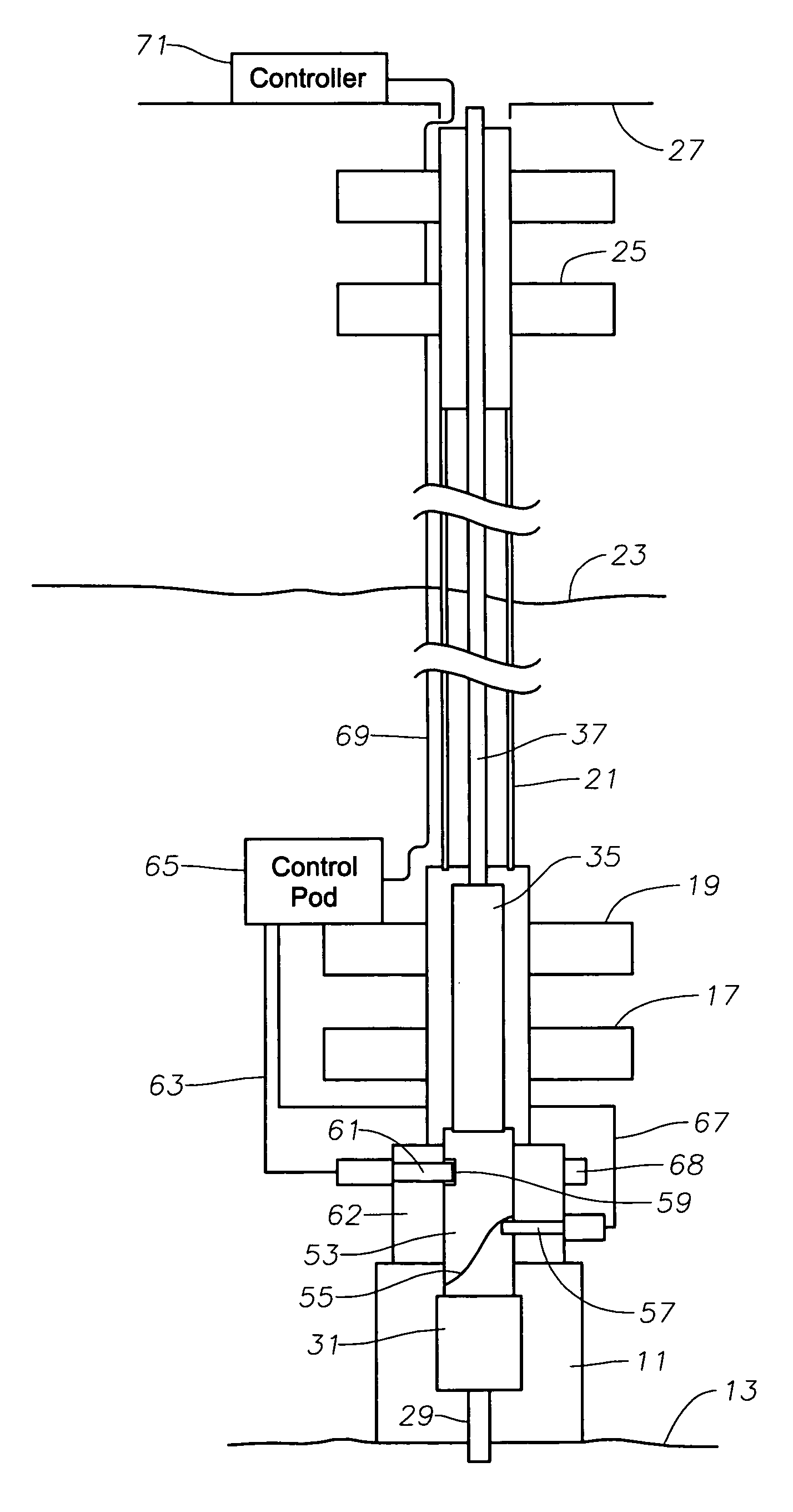
[0030]FIG. 4 discloses a In the embodiment of FIG. 4, running tool 53 has an orientation cam or slot 55 that is positioned to contact an orientation pin 57 mounted to the sidewall of adapter 62 below pipe rams 17. As cam slot 55 contacts orientation pin 57 while running tool 53 is being lowered, running tool 53 will rotate to a desired orientation relative to wellhead 11. Preferably, orientation pin 57 is retractable to not protrude into the bore of adapter 15 during normal drilling operations.

[0031]Running tool 53 has a receptacle 59 located on its sidewall that leads to various hydraulic and optionally electrical components of running tool 53. Receptacle 59 aligns with a reciprocal connector 61 when tubing hanger 31 is in the landing position and orientation pin 57 has properly oriented running tool 53. Reciprocal connector 61 is mounted to adapter 62 and has a plunger that extends out and sealingly engages receptacle 59.

first embodiment

[0032]A control line 63 extends from reciprocal connector 61 to a control pod 65. Control pod 65 is located subsea, preferably on a portion of the subsea pressure control equipment such as shear rams 19. Control pod 65 has electrical and hydraulic controls that preferably include a hydraulic accumulator that supplies pressurized hydraulic fluid-upon receipt of a signal. Control pod 65 connects to an umbilical 69 that is located on the exterior of riser 21, rather than in the interior as in the Umbilical 69 extends up to a controller 71 mounted on platform 27.

[0033]In the operation of the embodiment of FIG. 4, when running tubing hanger 31, the operator applies a signal to control pod 65 to cause orientation pin 57 to extend. Orientation pin 57 engages cam slot 55 and rotates running tool 53 to the desired alignment as running tool 53 moves downward. Control pod 65 provides the power via line 67 to stroke orientation pin 57, the power being either electrical or hydraulic. The operat...


PUM


Abstract

A method performing an operation in a subsea wellhead assembly through a riser extending between the wellhead assembly and a surface platform includes the step of connecting a surface blowout preventer to an upper portion of the riser. Then a tool is connected to a string of conduit. A control line is then connected to the tool, extended alongside the conduit. The tool and control line are lowered through the blowout preventer and riser. The method also includes the step of mounting a slick joint to an upper end of the conduit when the tool is near the wellhead assembly. The control line is then linked through the slick joint and extends to the surface platform. The method also includes the step of communicating with the tool via the control line and performing an operation in the wellhead assembly with the tool.

Description

RELATED APPLICATIONS[0001]Applicant claims priority to the application described herein through a U.S. provisional patent application titled “Tubing Running Equipment For Offshore Rig With Surface Blowout Preventer,” having U.S. patent application Ser. No. 60 / 606,588, which was filed on Sep. 2, 2004, and which is incorporated herein by reference in its entirety.BACKGROUND OF INVENTION[0002]1. Field of the Invention[0003]This invention relates in general to offshore drilling, and in particular to equipment and methods for running tubing or casing with an offshore rig that uses a surface blowout preventer.[0004]2. Background of the Invention[0005]When completing a subsea well for subsea production, a riser extends from a surface vessel and attaches to the subsea well. A tubing hanger is lowered with a conduit through the riser and landed in the tubing spool and wellhead assembly. A tubing hanger running tool that is connected to the upper end of the tubing hanger sets the seal and loc...

Claims


Application Information

Patent Timeline
Patent Type & Authority Patents(United States)
IPC IPC(8): E21B29/12E21B33/035E21B33/064E21B43/013
CPCE21B33/035E21B33/0355E21B33/064E21B41/0007E21B43/013E21B43/101
Inventor HOSIE, STANLEYCHRISTIE, DAVID S.MACDONALD, ALISTAIRMILNE, PAUL FINDLAY
Owner VETCO GRAY LLC
Learn More