Pump drive unit for battery operated fluid dispensers

a technology of battery-operated fluid dispensers and drive units, which is applied in the direction of positive displacement liquid engines, single-unit apparatuses, instruments, etc., can solve the problems of unsatisfactory pump performance, undesirable electric motor loading, and undesirably fast drainage of batteries, so as to reduce electric motor loading and improve pump performance , the effect of increasing the life of the battery

Inactive Publication Date: 2008-01-15
POWER SPRAYER +1
View PDF45 Cites 20 Cited by
  • Summary
  • Abstract
  • Description
  • Claims
  • Application Information

AI Technical Summary

Benefits of technology

[0005]In accordance with the present invention, battery operated fluid dispensers are provided with an improved pump drive unit by which the foregoing and other disadvantages are minimized or overcome. More particularly, in a pump drive unit according to the invention, the aligned cam and cam follower respectively associated with the electric motor and the pump element each have dual cam surfaces or faces cooperatively interengaging to achieve pump element displacement through the full stroke of the pump in a manner which provides balanced radial or lateral thrust forces on opposite sides of the motor shaft, cam follower and pump element. This relationship advantageously reduces not only the amount of wear between the cam components but the uneven wear thereof experienced with single cam face components. Moreover, balanced loading of the motor shaft, follower and pump element reduces undesirable loading of the electric motor and thus battery drain, thus providing a longer life for the drive system, improved battery life, and improved performance of the pump element.
[0006]Another improvement in accordance with the invention resides in providing rollers on laterally opposite sides of the cam follower which ride in corresponding slots in the cam follower support. The rollers and slots interengage to preclude rotation of the cam follower relative to its support, and the interengagement between the slots and rollers advantageously reduces friction between the component parts during axial movement of the cam follower.
[0009]A further object is the provision of a pump drive unit of the foregoing character which provides for a more uniform wearing of the interengaging cam surfaces than achieved with cam drive arrangements heretofore provided.
[0010]Yet another object is the provision of a pump drive unit of the foregoing character providing improved performance of the pump during the operation of the pump.
[0011]Yet a further object is the provision of a pump drive unit of the foregoing character which reduces loading of the electric motor, thus increasing the life thereof and reducing battery drainage so as to improve battery life.
[0012]Still another object is the provision of a pump drive unit of the foregoing character which results in improved performance of the pump element during operation thereof.

Problems solved by technology

While the battery operated dispenser in the Nottingham, et al. patent operates satisfactorily, component parts in the pumping mechanism are subjected to forces and frictional interengagement which causes undesirable wear of the parts, undesirable loading of the electric motor, and undesirably fast drainage of the batteries.
Such loading of the cam faces not only promotes wear therebetween but uneven wear.
Moreover, radial loading of the cam follower urges the latter against the cylinder portion of the pump and, together with radial loading of the motor shaft, imposes loads on the motor which in turn causes undesirably high drainage of the batteries.
All of these undesirable loading characteristics impose frictional interengagement between the parts which undesirably affects performance of the drive unit and pump element.
Moreover, maintenance and / or part replacement resulting from wearing of the component parts and battery drainage is undesirably high.

Method used


Image

  • Pump drive unit for battery operated fluid dispensers
  • Pump drive unit for battery operated fluid dispensers
  • Pump drive unit for battery operated fluid dispensers

Examples


Embodiment Construction

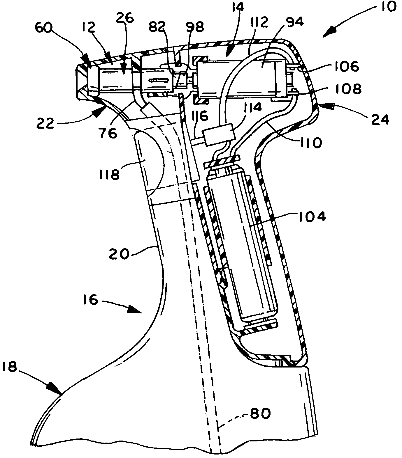
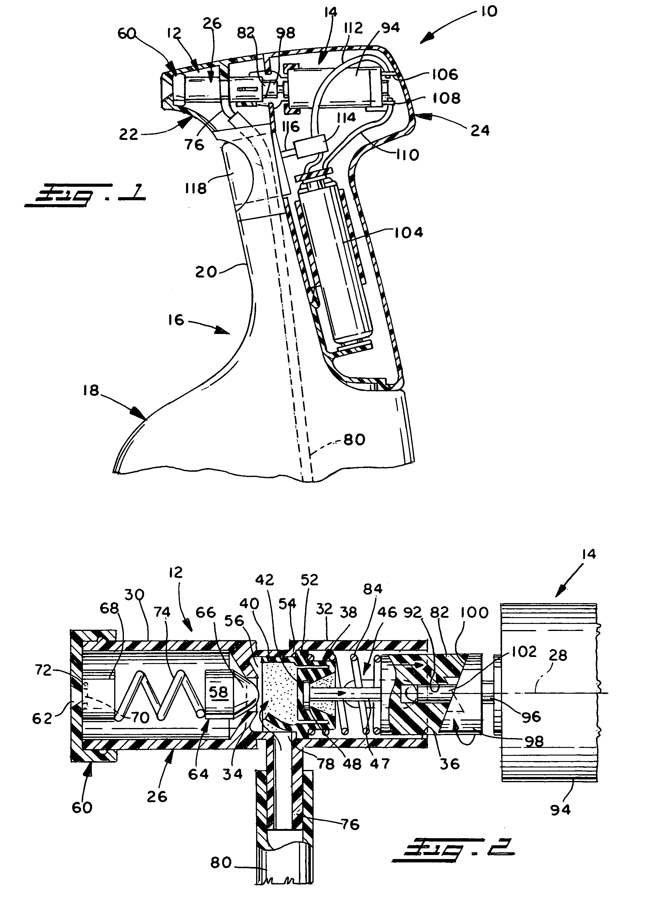
[0022]Referring now in greater detail to the drawings, wherein the showings are for the purpose of illustrating preferred embodiments of the invention only, and not for the purpose of limiting the invention, FIG. 1 illustrates a fluid dispenser 10 comprising a pumping unit 12 and a pump driving unit 14 mounted on a supply container 16. Container 16 includes a lower body portion 18, only a portion of which is shown, and a narrow neck portion 20 extending upwardly therefrom, and pumping unit 12 and pump drive unit 14 are respectively enclosed in housings 22 and 24 contoured to provide a desired spray head profile with one another and with adjacent portions of container 16.

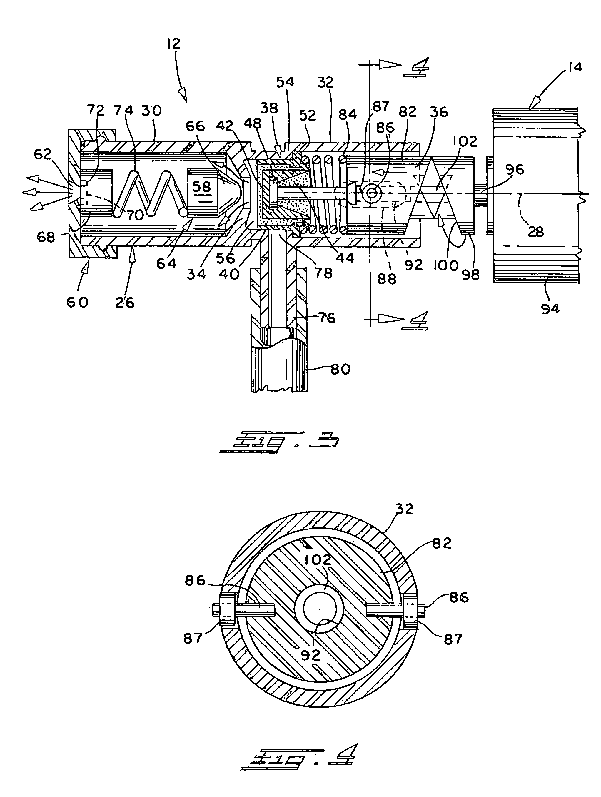
[0023]As best seen in FIGS. 2 and 3, pumping unit 12 includes a cylindrical body member 26 having an axis 28 and providing an axially outer discharge tube portion 30 and an axially inner pump portion 32, which portions 30 and 32 are separated internally of member 26 by a radially inwardly extending peripheral wall 34...


PUM


Abstract

A battery operated, handheld fluid dispenser comprises a supply container having a body portion and a narrow neck extending upwardly therefrom. A pump and discharge unit is mounted on the upper end of the neck and comprises a pump diaphragm and pump chamber for pumping liquid from the container to a discharge nozzle. A battery powered pump drive unit is mounted on the container and comprises an electric motor having an output shaft coupled with the pump diaphragm through a cam and cam follower arrangement to displace the diaphragm through a pump stroke when the motor is energized. The cam is rotatably driven by the motor, and the cam follower is attached to the diaphragm, whereby rotation of said cam axially displaces the diaphragm, and the cam and cam follower have interengaging dual cam faces for balancing lateral forces therebetween during rotation of said cam relative to said cam follower.

Description

CROSS-REFERENCE TO RELATED APPLICATIONS[0001]This application claims priority from U.S. Provisional Patent Application Ser. No. 60 / 465,438 filed Apr. 28, 2003.BACKGROUND OF THE INVENTION[0002]This invention relates to the art of handheld fluid dispensers and, more particularly, to improvements in the pump drive unit of a battery operated, handheld fluid dispenser.[0003]A battery operated, motorized fluid dispenser of the character to which the present invention is directed is shown, for example, in U.S. Pat. No. 5,716,007 to Nottingham, et al. which is assigned to the same assignee as the present invention and which is hereby incorporated herein by reference. In the latter dispenser, an electric motor is selectively connected to a battery source by a push button or trigger operated switch and, when energized, the motor operates a pump mechanism by which fluid in a supply container associated with the dispenser is pumped through a discharge opening.[0004]While the battery operated di...

Claims


Application Information

Patent Timeline
IPC IPC(8): B65D88/54F16H53/00B05B9/08B05B11/00
CPCB05B9/0861Y10T74/2107Y10T74/2101B05B11/3032
Inventor VITANTONIO, MARC L.SAUNDERS, CRAIG M.FUCHS, JR., DONALD C.WANHAINEN, DANIEL J.
Owner POWER SPRAYER
Why Eureka
Try Eureka