Control device for vehicular drive system
a control device and drive system technology, applied in the direction of electric propulsion mounting, transportation and packaging, jet propulsion mounting, etc., can solve the problems of unfavorable drive system size, unfavorable drive system operation, so as to reduce the operating shock of the drive system and improve the fuel economy of the vehicle.
- Summary
- Abstract
- Description
- Claims
- Application Information
AI Technical Summary
Benefits of technology
Problems solved by technology
Method used
Image
Examples
first embodiment
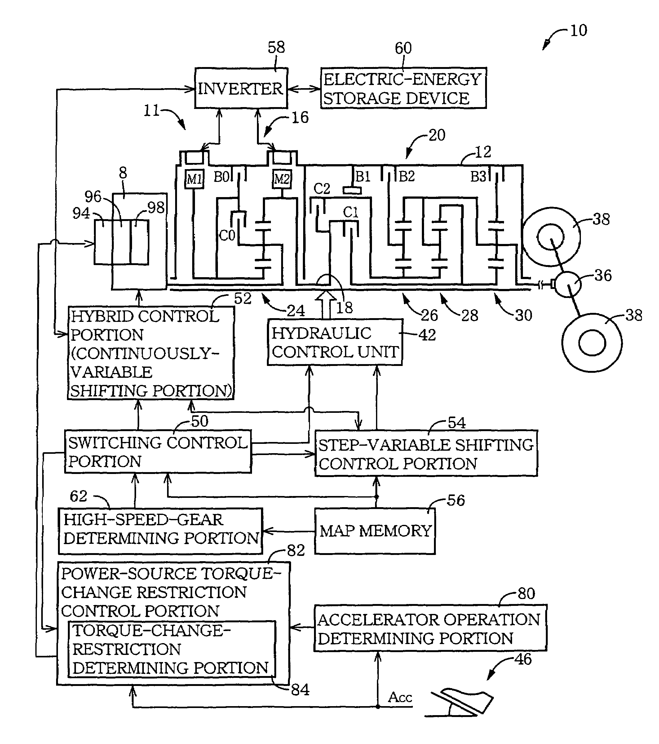
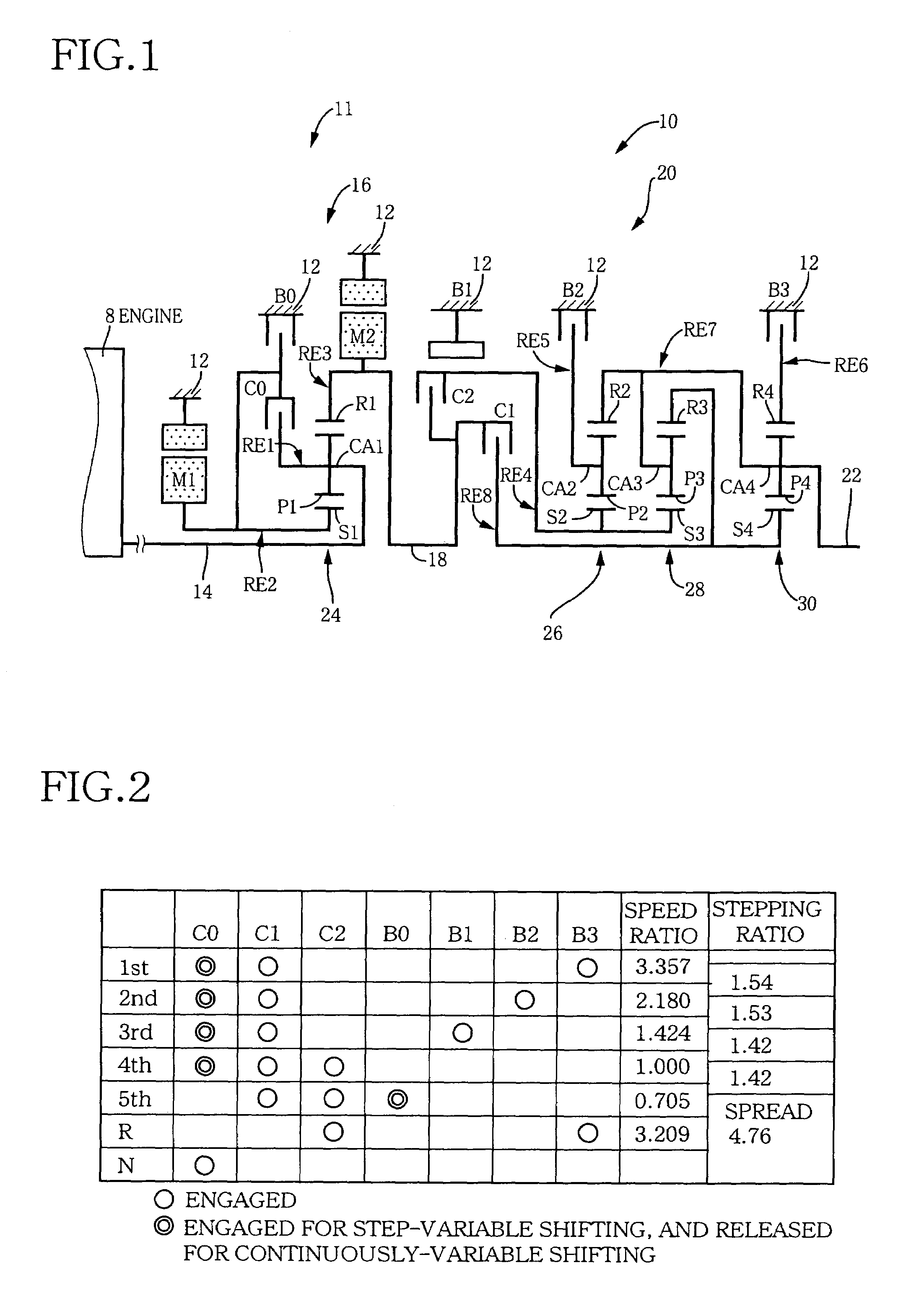
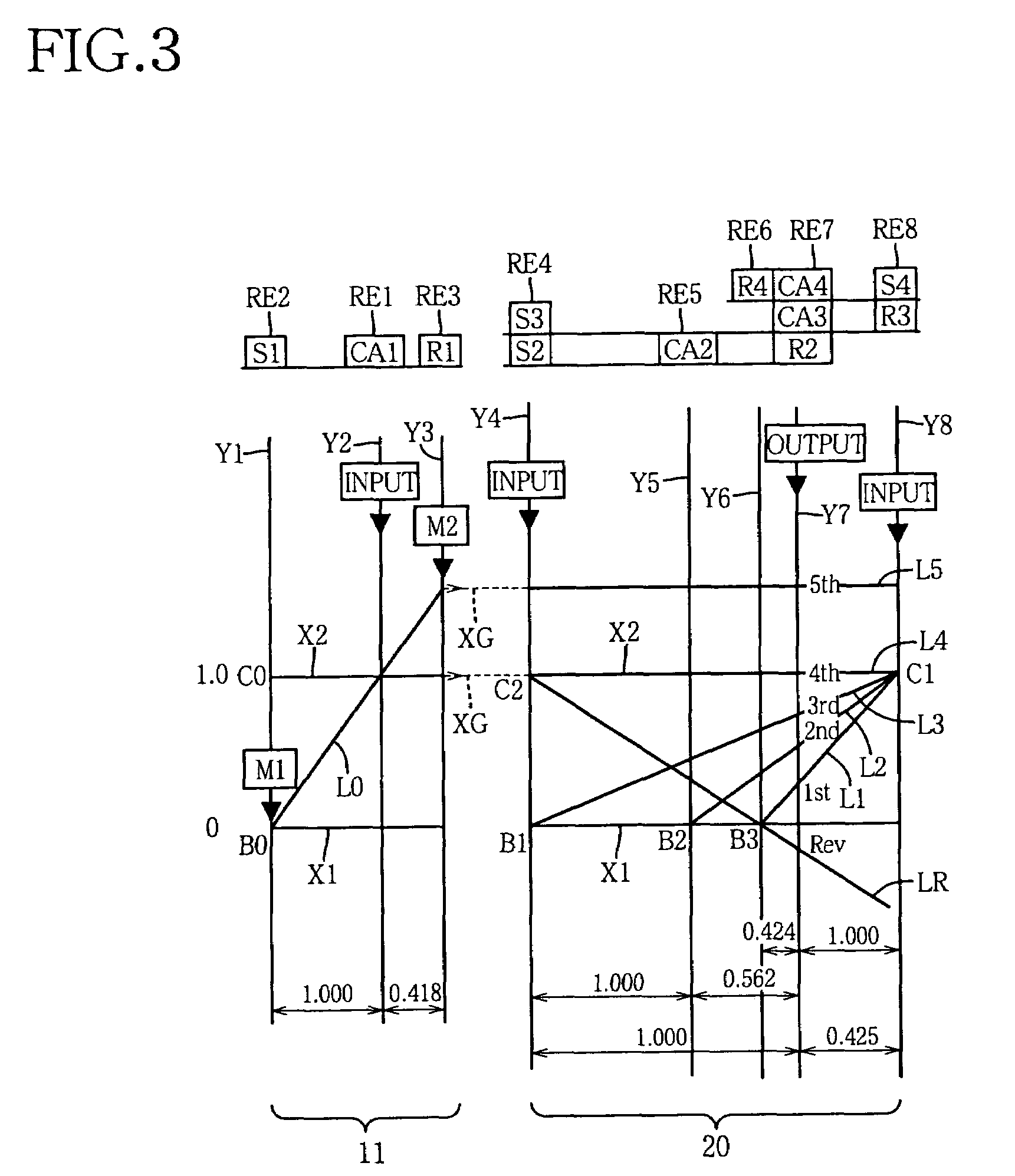
[0059]FIG. 1 is a schematic view explaining a transmission mechanism 10 constituting a part of a drive system for a hybrid vehicle, which drive system is controlled by a control device according to one embodiment of this invention. The transmission mechanism 10 includes: an input rotary member in the form of an input shaft 14 disposed on a common axis in a transmission casing 12 functioning as a stationary member attached to a body of the vehicle; a continuously-variable transmission portion 11 connected to the input shaft 14 either directly, or indirectly via a pulsation absorbing damper (vibration damping device) not shown; a step-variable or multiple-step automatic transmission portion 20 interposed between and connected in series via a power transmitting member 18 (power transmitting shaft) to the continuously-variable transmission portion 11 and drive wheels 38 (shown in FIG. 5) of the vehicle; and an output rotary member in the form of an output shaft 22 connected to the autom...
second embodiment
[0117]Referring to the block diagram of FIG. 12, there is shown a control device according to a second embodiment of this invention, which is arranged to execute a switching-shock reducing routine illustrated in the flow chart of FIG. 13. While this control device according to the second embodiment is arranged to control the drive system including the engine 8 and the transmission mechanism 10 as shown in FIGS. 1 and 5, the control device includes a torque-reduction control portion 86 and an engagement-terminal-phase determining portion 88, in place of the power-source torque-change restriction control portion 82 provided in the first embodiment.
[0118]The engagement-terminal-phase determining portion 88 is arranged to determine whether the switching clutch C0 or brake B0 to be engaged to establish the step-variable shifting state is in a terminal phase of its engaging action, which is initiated when the switching control portion 50 has determined that the transmission mechanism 10 s...
third embodiment
[0142]Referring to the schematic view of FIG. 15, there is shown an arrangement of a transmission mechanism 70 of a vehicular drive system according to a third embodiment of this invention, which may be controlled by the electronic control device in the first or second embodiment. Although the transmission mechanism 70 is different from the transmission mechanism 10 according to the first embodiment of FIGS. 1-11, the transmission mechanism 70 is controlled by an electronic control device which is substantially identical with the electronic control unit 40 described above with respect to the first embodiment of FIGS. 1-11 or the second embodiment of FIGS. 12-14. FIG. 16 is a table indicating gear positions of the transmission mechanism 70, and different combinations of engaged states of the hydraulically operated frictional coupling devices for respectively establishing those gear positions, while FIG. 17 is a collinear chart for explaining a shifting operation of the transmission m...
PUM
 Abstract
Description
Claims
Application Information
 - R&D
- Intellectual Property
- Life Sciences
- Materials
- Tech Scout
- Unparalleled Data Quality
- Higher Quality Content
- 60% Fewer Hallucinations
Browse by: Latest US Patents, China's latest patents, Technical Efficacy Thesaurus, Application Domain, Technology Topic, Popular Technical Reports.
© 2025 PatSnap. All rights reserved.Legal|Privacy policy|Modern Slavery Act Transparency Statement|Sitemap|About US| Contact US: help@patsnap.com


