Acoustic concealed item detector

a concealed item and detector technology, applied in the field of concealed item detection, can solve the problems of ultrasonic waves that are typically difficult to penetrate difficult to detect concealed items behind fabric or material-covered targets or suspect areas, etc., and achieve the effect of accurately interrogating a person and better detecting clothing

Active Publication Date: 2008-01-15
LUNA LABS USA LLC
View PDF15 Cites 29 Cited by
  • Summary
  • Abstract
  • Description
  • Claims
  • Application Information

AI Technical Summary

Benefits of technology

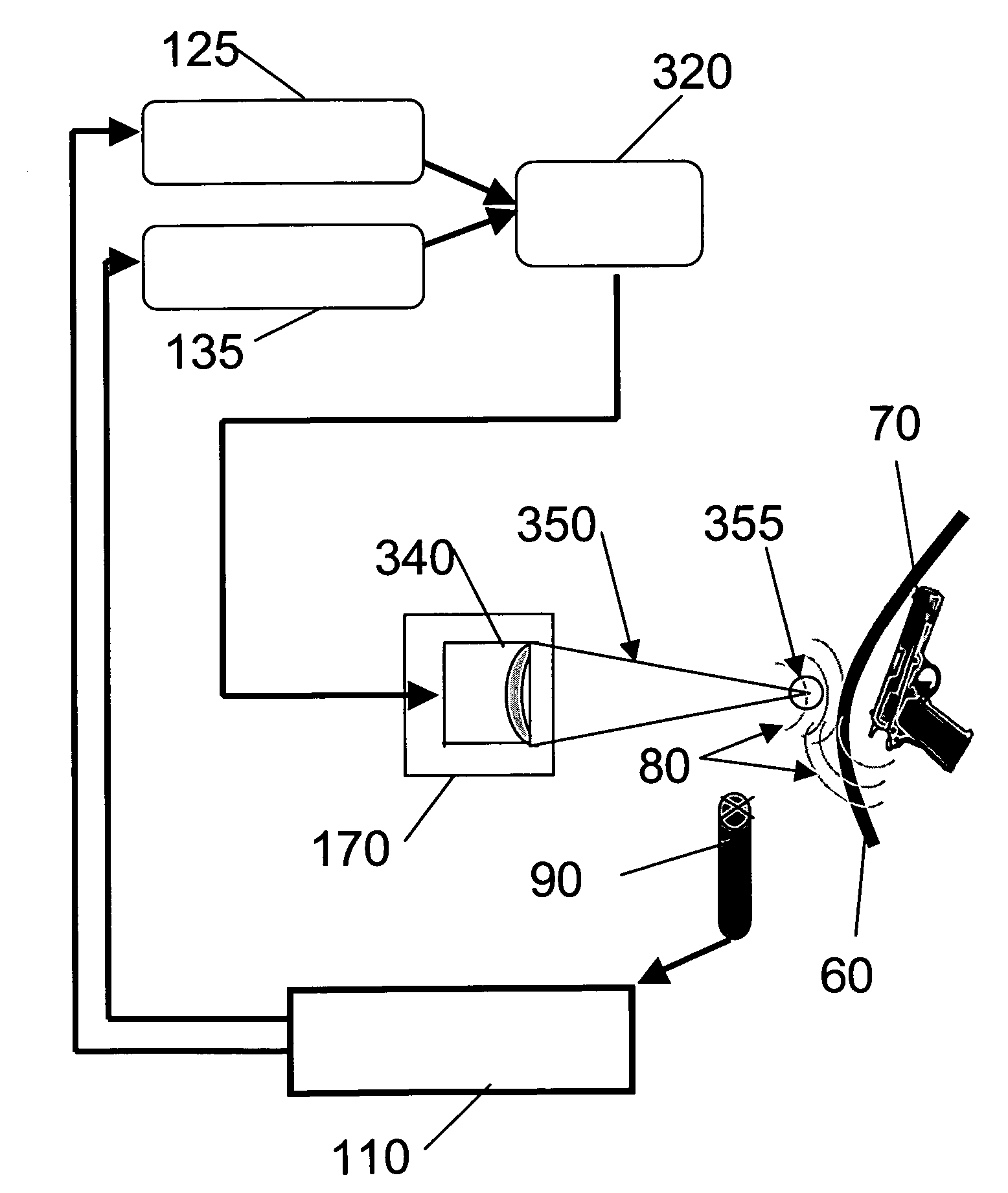
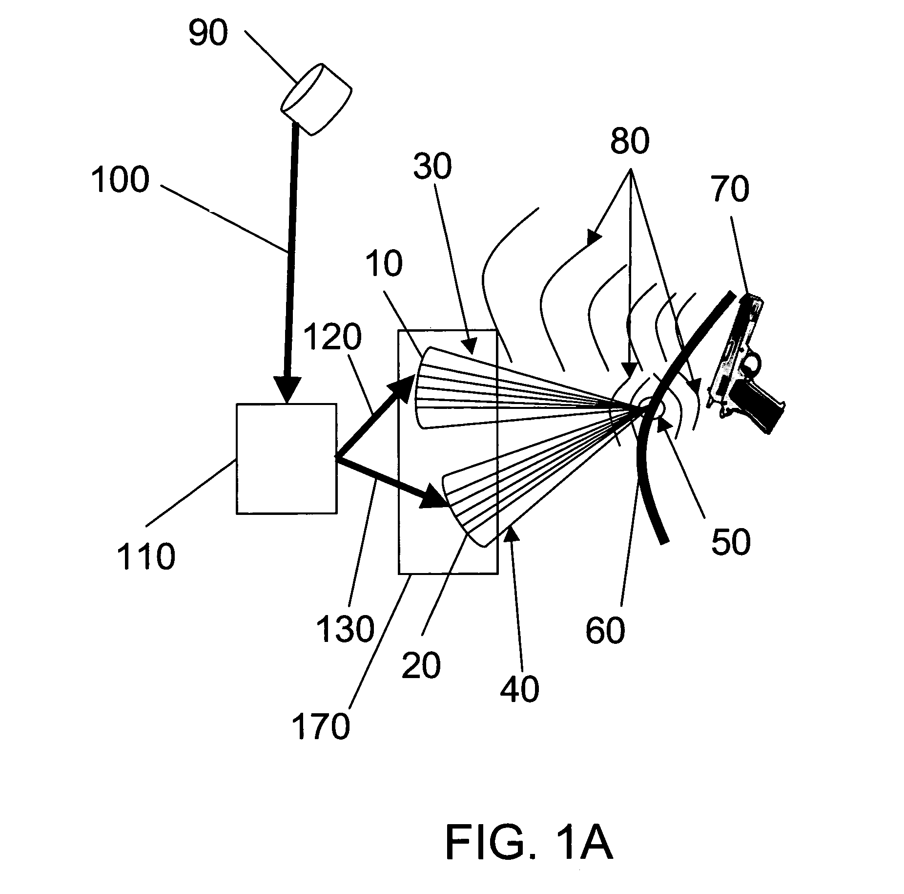
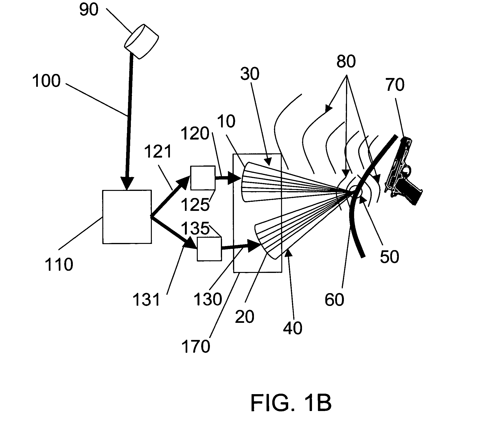
[0035]The localized acoustic wave is most preferably generated by the interaction of ultrasonic waves to produce a difference-frequency acoustic wave in the desired frequency range. This is possible because interactions of a first ultrasonic wave of frequency f1 with second ultrasonic wave of frequency f2 produce waves with frequencies f1, f2, f1+f2, and f1−f2, (if f1<f2 then the relevant frequency is f2−f1) as well as a static radiation pressure. (Acoustic radiation pressure is defined as the difference between the average pressure at a surface and the pressure that would have existed at the surface absent the acoustic wave.) In preferred embodiments, with appropriate choices of the frequencies f1 and f2, the difference frequency f1−f2 is in the audible range. This audible acoustic wave can better penetrate clothing and if localized, can also accurately interrogate a person for hidden weapons. Additional ultrasonic waves with additional frequencies can also be used to simultaneously obtain multiple difference-frequency waves or to exploit higher-order non-linear effects.
[0036]The acoustic concealed item detector gives the user the ability to focus a probing energy on a small zone and scan that zone over the object. The acoustic wave generated at the zone “sees” through clothing and can assess hidden shapes from the acoustic interaction at the zone and with the hidden weapon.

Problems solved by technology

Detecting a concealed item behind a fabric or material-covered target or suspect area is particularly difficult with ultrasonic waves.
Ultrasonic waves typically have trouble penetrating fabric or material-covered targets.

Method used


Image

  • Acoustic concealed item detector
  • Acoustic concealed item detector
  • Acoustic concealed item detector

Examples


Embodiment Construction

[0050]Non-linear acoustics can be better understood physically by modeling the transmission medium and including the effect of the acoustic pressure on the density. For most applications considered here, the transmission medium is a gas, most typically air.

[0051]The density, ρ, of the transmission medium depends on the acoustic environment:

ρ=ρ0(1+δ)

where ρ0 is the static density and δ is the incremental increase in density produced by the acoustic wave.

[0052]The acoustic pressure is then

P=ρ0cA(1+δ),

where c is the acoustic propagation velocity and A is the “particle velocity” that a small element within the transmission medium sees when in the presence of an acoustic wave.

[0053]For two interacting waves of sinusoidal excitation of frequencies f1 and f2 with corresponding wave-numbers k1 and k2:

A=A1 sin(2πf1t−k1x)+A2 sin(2πf2t−k2x).

Therefore, the dynamic pressure is expressed as:

P=ρ0c[A1 sin X+A2 sin Y]+ρ0cδ0[A1 sin X +A2 sin Y]2,

where X and Y are the corresponding angular arguments: ...


PUM


Abstract

The present invention is directed towards an acoustic concealed item detector and related methods for detection using acoustics. In an illustrative embodiment, a multi-frequency ultrasonic wave generator generates in a gaseous medium at least first and second ultrasonic waves. The multi-frequency ultrasonic wave generator is arranged such that in operation, the first ultrasonic wave and the second ultrasonic wave mix in a prescribed mixing zone to produce a difference-frequency acoustic wave. A receiver sensor detects the difference-frequency acoustic wave and produces corresponding electromagnetic signals. The electromagnetic signals are processed by a system processor and signals indicative of concealed items are identified. Preferably the ultrasonic waves are focused to a small prescribed mixing zone. Parametric and multi-transducer embodiments are disclosed.

Description

CROSS-REFERENCE TO RELATED APPLICATIONS[0001]This application claims priority under USC 119(e) of provisional patent application Ser. No. 60 / 638,339 filed Dec. 20, 2004 entitled “NON-LINEAR ACOUSTIC CONCEALED WEAPONS DETECTOR,” which is hereby incorporated by reference in its entirety.GOVERNMENT LICENSE RIGHTS[0002]The U.S. Government has a paid-up license in this invention and the right in limited circumstances to require the patent owner to license others on reasonable terms as provided for by the terms of contract No. FA8750-04-C-0043 awarded by the Air Force Research Lab for the Department of Justice.FIELD OF THE INVENTION[0003]The present invention relates to detection of concealed items. In particular, it relates to acoustic concealed item detectors.BACKGROUND OF THE INVENTION[0004]Detecting concealed weapons has been a major concern of law enforcement for decades, but today's most widely used technology, metal detectors, only provide a partial solution. Metal detectors can on...

Claims


Application Information

Patent Timeline
Patent Type & Authority Patents(United States)
IPC IPC(8): G01S15/89G01S15/66
CPCG01V1/001
Inventor HEYMAN, JOSEPH S.
Owner LUNA LABS USA LLC
Why Eureka
Try Eureka