Pivotal sheet conveying apparatus for skew correction and image forming apparatus

a conveying apparatus and skew technology, applied in the field of skew correction and image forming apparatus, can solve the problems of changing the ability to correct the skew conveying, generating noise (so-called loop noise), and jamming of paper plugging, so as to prevent the position shift of the sheet, the effect of enhancing the accuracy of the skew correction

Inactive Publication Date: 2008-01-15
CANON KK
View PDF18 Cites 25 Cited by
  • Summary
  • Abstract
  • Description
  • Claims
  • Application Information

AI Technical Summary

Benefits of technology

[0019]The present invention has been made in the light of such an existing condition, and it is, therefore, an object of the present invention to provide a sheet conveying apparatus which is capable of enhancing the accuracy of correcting a skew of a sheet, and of preventing position shift of a sheet, and an image forming apparatus and an image reading apparatus.

Problems solved by technology

However, in such a loop registration method, a loop space for formation of the loop is necessarily required to scale up the apparatus.
In addition, when a sufficient loop space cannot be ensured, in particular, there is encountered a problem in that jam (paper plugging) due to the buckling is generated in a sheet having weak stiffness such as a thin paper, and when the sheet is brought into contact with the registration roller pair, a noise (so-called a loop noise) is generated.
Moreover, there is encountered a problem in that an ability to correct the skew conveying is changed by the strength of the stiffness of the sheet.
More specifically, in case of a thin paper having weak stiffness, the abutting pressure when the leading edge of the sheet is brought into contact with the registration roller nip becomes insufficient, and hence the leading edge of the sheet cannot be sufficiently brought into contact with the registration roller pair in some cases.
In such cases, the skew conveying correction cannot be perfectly carried out.
In addition, in case of a sheet having large stiffness such as a thick paper, there is nonconformity that the sheet goes through the nip of the registration roller pair due to a shock caused when the leading edge of the sheet is brought into contact with the nip of the registration roller pair.
Then, if a load or the like is tried to be applied to the registration roller pair by a brake member for example in order to prevent this nonconformity, this causes cost-up of a product.
Furthermore, in a case or the like where a leading edge of a sheet is curled or folded, the leading edge of the sheet cannot be made accurately parallel to the nip portion of the registration roller pair.
As a result, there is also encountered a problem in that the skew conveying correction cannot be accurately carried out to reduce the printing accuracy.
Thus, even in copying for a plurality of sheets of papers, a mechanical motion as in an optical device becomes unnecessary.
Here, when as described above, the pivotal movement center exists at the shaft end of the conveying roller pair, there is nonconformity that if the conveying roller pair is pivotally moved about the pivotal movement center, since a point at which the skew amount of sheet is detected is largely moved along with the pivotal movement of the conveying roller pair, the skew of the sheet cannot be accurately corrected.
Moreover, in particular, in the image forming apparatus for writing an image on the basis of a signal from a sensor, there is nonconformity that if the point at which the (the skew amount of) sheet is detected is largely shifted in such a manner, a position where an image is written to the sheet is shifted accordingly, and hence the suitable image formation cannot be carried out.

Method used


Image

  • Pivotal sheet conveying apparatus for skew correction and image forming apparatus
  • Pivotal sheet conveying apparatus for skew correction and image forming apparatus
  • Pivotal sheet conveying apparatus for skew correction and image forming apparatus

Examples


first embodiment

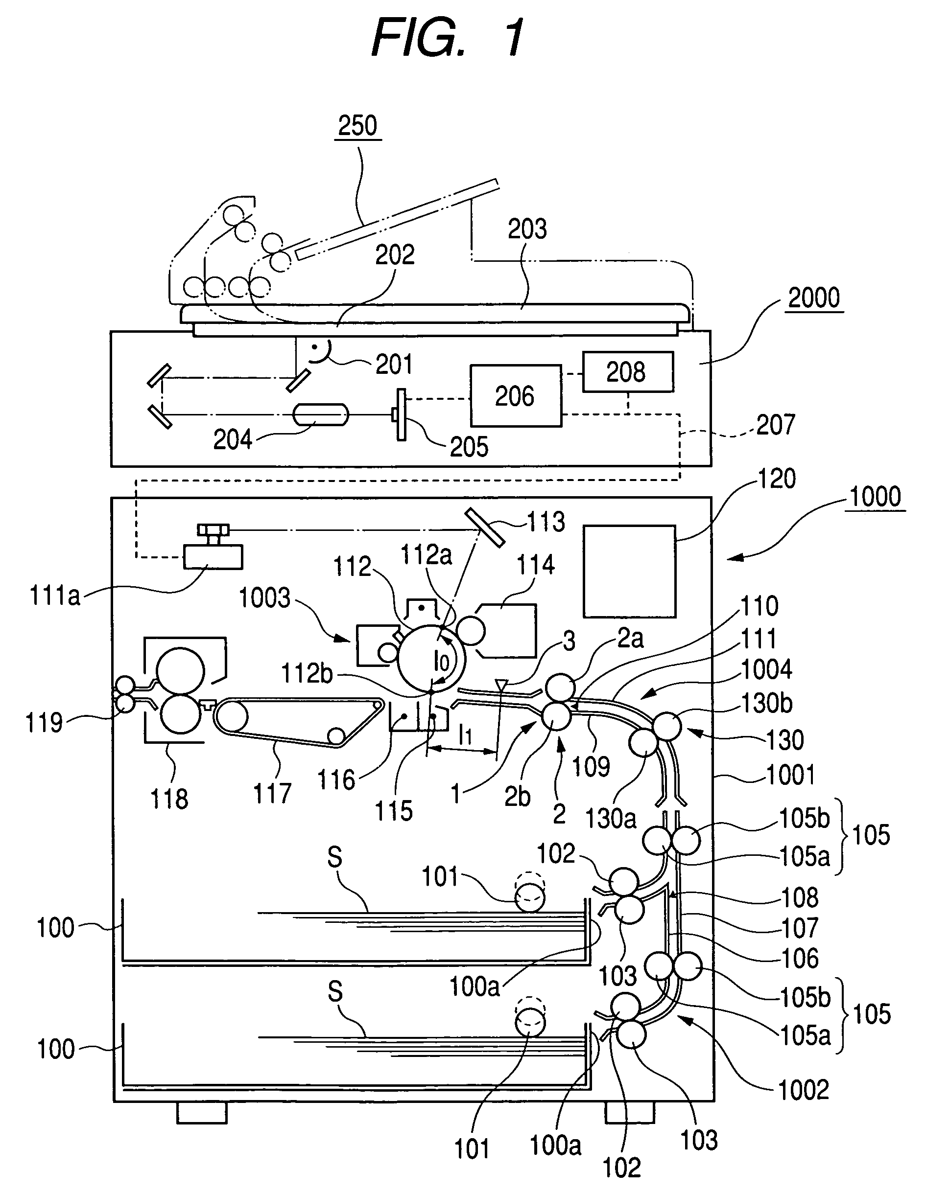
[0043]FIG. 1 is a cross sectional view of a printer as an example of an image forming apparatus including a sheet conveying apparatus according to the present invention.

[0044]In the figure, reference numeral 1000 designates a printer which includes a printer main body 1001 and a scanner 2000 disposed on an upper surface of the printer main body 1001.

[0045]Here, the scanner 2000 for reading image information of an original includes a scanning optical system light source 201, a platen glass 202, an original pressing plate 203 adapted to be opened and closed, a lens 204, a light receiving element (photoelectric conversion element) 205, an image processing portion 206, a memory portion 208 for storing therein an image processing signal obtained through the processing in the image processing portion 206, and the like.

[0046]Then, when image information of an original (not shown) is read, light is applied to the original placed on the platen glass 202 by the scanning optical system light s...


PUM


Abstract

To provide a sheet conveying apparatus capable of enhancing an accuracy of correcting a skew of a sheet, and of preventing position shift of a sheet. The present invention provides a sheet conveying apparatus for conveying a sheet by a sheet conveying unit disposed along a sheet conveying path, including: a skew detection sensor for detecting a skew of the sheet with respect to a sheet conveying direction by a plurality of detection sensors disposed in a direction intersecting perpendicularly the sheet conveying direction; and a skew correction roller adapted to be pivotally moved in a direction of correction of a skew of the sheet in a state with the skewed sheet being held on the basis of a detection signal from the skew detection sensor, in which one of the plurality of detection sensors of the skew detection sensor is disposed nearly on an extension line from a pivotal movement center of the skew correction roller in the sheet conveying direction.

Description

[0001]This application claims priority from Japanese Patent Application No. 2003-198787 filed Jul. 17, 2003, which is hereby incorporated by reference.BACKGROUND OF THE INVENTION[0002]1. Field of the Invention[0003]The present invention relates in general to a sheet conveying apparatus provided in an image forming apparatus, and more particularly to a construction for correcting a skew of a sheet being conveyed.[0004]2. Related Background Art[0005]Heretofore, an image forming apparatus or an image reading apparatus such as a copying machine, a printer, a facsimile or a scanner is provided with a sheet conveying apparatus for conveying a sheet such as a recording paper or an original to an image forming portion or an image recording portion. Then, some of the sheet conveying apparatuses includes correction means for carrying out skew conveying correction for a sheet and position shift correction for a sheet in order to adjust an attitude and a position of the sheet before the sheet i...

Claims


Application Information

Patent Timeline
Patent Type & Authority Patents(United States)
IPC IPC(8): G03G21/00B65H7/08G03G21/14B65H7/10B65H9/00B65H9/20G03G15/00G03G15/04H04N1/00
CPCB65H7/10B65H9/20B65H2511/212B65H2511/242B65H2511/51B65H2513/511B65H2557/51B65H2220/02B65H2220/11B65H2220/03B65H2220/01B65H2513/51B65H2511/24
Inventor KOYANAGI, NORIAKISUGA, TAKESHI
Owner CANON KK
Why Eureka
Try Eureka