Engine revolution controller of working machine

a technology of working machine and revolution controller, which is applied in the direction of electric control, ignition automatic control, machines/engines, etc., can solve the problems of reducing the output of the engine, affecting the operation of the engine, so as to reduce the opening of the throttle, reduce the increase of the revolution speed, and sacrifice the effect of outpu

Inactive Publication Date: 2008-01-22
HONDA MOTOR CO LTD
View PDF9 Cites 3 Cited by
  • Summary
  • Abstract
  • Description
  • Claims
  • Application Information

AI Technical Summary

Benefits of technology

[0013]According to the first feature, in this engine, the revolution speed is manually controlled using the throttle opening operating device without providing the mechanical governor means, that is, governor mechanism, but the engine revolution speed can be maintained close the preset revolution speed while keeping the throttle opening constantly (for example, fully open) without operating the throttle opening operating device in a region where the engine revolution speed is equal to or higher than the predetermined revolution speed.
[0014]When the throttle is fully opened, the revolution speed is maintained at the value closer to the set revolution speed by lagging the ignition timing, but when a load is increased, since the lagged ignition timing is returned to the advanced side, it is possible to cope with the load variation in a state where the predetermined value of the engine revolution speed is maintained. Since it is possible to suppress the increase of the revolution speed while fully opening the throttle, it is possible to sufficiently exhibit the engine ability near the predetermined revolution speed at least. When load is extremely low or there is no load, the engine revolution speed cannot be suppressed only by lagging the ignition timing in some cases. The throttle opening is reduced by the throttle opening operating device only in such a case. With this, it is possible to sufficiently cope with this problem. That is, in a state where a load of a certain value is applied, it is almost unnecessary to adjust the throttle opening.
[0015]According to the second feature, the throttle opening is limited to the closer side than the fully opened position. With this, it is possible to carry out the operation without adjusting the throttle opening until the operation state reaches the light load region from the rating operation.
[0016]According to the third feature, it is possible to utilize the revolution controller in the same manner as that of the engine revolution controller of a working machine having a governor mechanism. That is, it is possible to maintain the engine revolution speed at substantially constant value only by adjusting the ignition timing without adjusting the throttle opening.
[0017]Further, since the upper limit of the throttle opening is limited such that the predetermined revolution speed is set to the substantially no load operation revolution speed, it is possible to rise from the stable operation in the no load operating region swiftly. Thus, although the upper limit of the throttle is limited, the sacrifice of output is small as compared with the conventional throttle opening limitation, and the engine ability can be exhibited effectively.
[0018]According to the fourth feature, by setting appropriate ignition timing with respect to the engine revolution speed in accordance with feature of a working machine which is a load in an engine for driving a working machine, that is, a general engine, it is possible to maintain the operation at stable revolution speed with respect to the load variation of the operation.

Problems solved by technology

However, since an engine used as a power source such as a handheld mower and a blower is used at relatively high speed rotation, stable control result can not be obtained easily by the conventional governor mechanism, and since it is desired to reduce the working machine in size and weight, the engine is not provided with the governor mechanism in many cases.
If the engine revolution speed becomes higher, the operation noise caused by the revolution of the engine is abruptly increased, and this is not preferable in terms of vibration and endurance.

Method used


Image

  • Engine revolution controller of working machine
  • Engine revolution controller of working machine
  • Engine revolution controller of working machine

Examples


Embodiment Construction

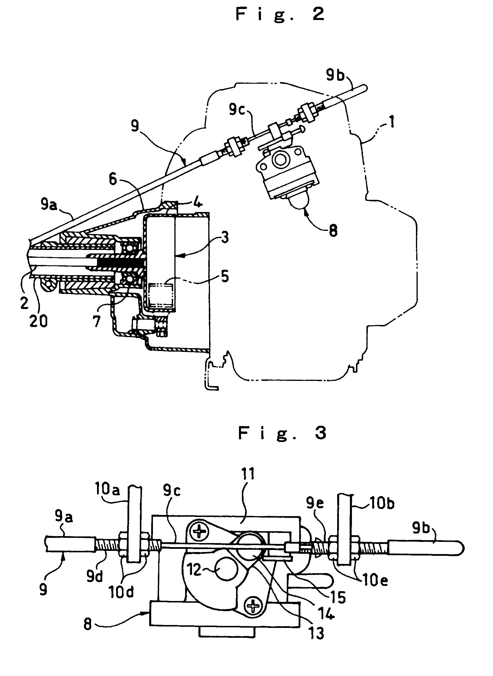
[0030]An embodiment of the present invention will be explained in detail with reference to the drawings. FIG. 8 is a perspective view of a mower having an engine including a revolution controller according to the embodiment of the invention. FIG. 2 is a sectional view of a front portion of the engine. FIG. 3 is a plan view of a carburetor. In FIG. 8, the mowing machine 100 includes an engine 1, an operating sleeve 20 which extends from the engine 1 and which is provided at its tip end with a cutting blade 110, a handle 120 provided at an intermediate portion of the operating sleeve 20, and an operating device 16 which is provided on a right side end of the handle 120 and which also functions as a grip. The mowing machine 100 further includes a throttle cable 9 extending from the operating device 16 to a carburetor 8 of the engine. The engine 1 is a small sized (for example, displacement of 25 cm3) air-cooled four stroke single-cylinder engine which is suitable for the mowing machine...


PUM


Abstract

In an engine of a working machine having no governor mechanism, the engine revolution speed is controlled such that the revolution speed can stably be maintained irrespective of the variation in load without adjusting the throttle opening to exploit the full potential of the engine. Since an engine 1 does not have the governor mechanism, an operator adjusts the throttle opening and controls the engine revolution speed. A map in which ignition timing (amount of angle of lead) is set by means of functions of the engine revolution speed is stored in an ignition timing map 30. The map 30 is set such that the engine revolution speed is equal to or higher than a value to be controlled (e.g. 7000 rpm), and the ignition timing is lagged as compared with a case in which the engine revolution speed is lower than the value to be controlled.

Description

TECHNICAL FIELD[0001]The present invention relates to a revolution controller of an internal combustion engine (simply referred to as “engine”, hereinafter) for a working machine, and more particularly, to an engine revolution controller for a working machine capable of controlling the engine revolution speed without providing a governor mechanism, or mechanical governor means.BACKGROUND ART[0002]In an engine for driving a working machine such as a small type general engine, typically, the engine revolution speed is appropriately controlled by using a governor mechanism. As the governor mechanism, there is a known mechanism in which a link mechanism is moved by a centrifugal force suitable for the engine revolution speed, the movement of the link mechanism is transmitted to a throttle valve, and the throttle opening is adjusted. However, since an engine used as a power source such as a handheld mower and a blower is used at relatively high speed rotation, stable control result can n...

Claims


Application Information

Patent Timeline
Patent Type & Authority Patents(United States)
IPC IPC(8): F02P5/15F02D43/00F02D9/02F02D11/02F02P5/06
CPCF02B63/02F02D11/02F02P5/1502F02D2011/102F02D2400/06F02P1/00F02P5/1555F02P9/005Y02T10/46Y02T10/40
Inventor TAMAMOTO, RIYUUHEIYONEYAMA, TADAYUKIYAMAMURA, MAKOTOKANAI, MITSUYOSHI
Owner HONDA MOTOR CO LTD
Why Eureka
Try Eureka