

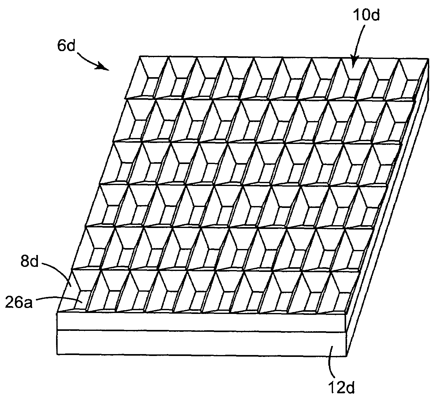
Optical film having a structured surface with concave pyramid-shaped structures
a technology of optical films and structured surfaces, applied in the field of light-transmissive optical films, can solve the problems of reducing power allocation, not self-illuminating, and increasing the energy consumption of additional light sources and/or brighter light sources
- Summary
- Abstract
- Description
- Claims
- Application Information
AI Technical Summary
Benefits of technology
Problems solved by technology
Method used
Image

Examples
Embodiment Construction
[0031]The present disclosure is directed to optical films capable of controlling the distribution of light from a light source and, in some exemplary embodiments, capable of controlling light distribution along two different directions. The optical film according to the present disclosure may be useful in controlling the light distribution for an LCD backlight (e.g., backlights shown in FIGS. 1A-1D).
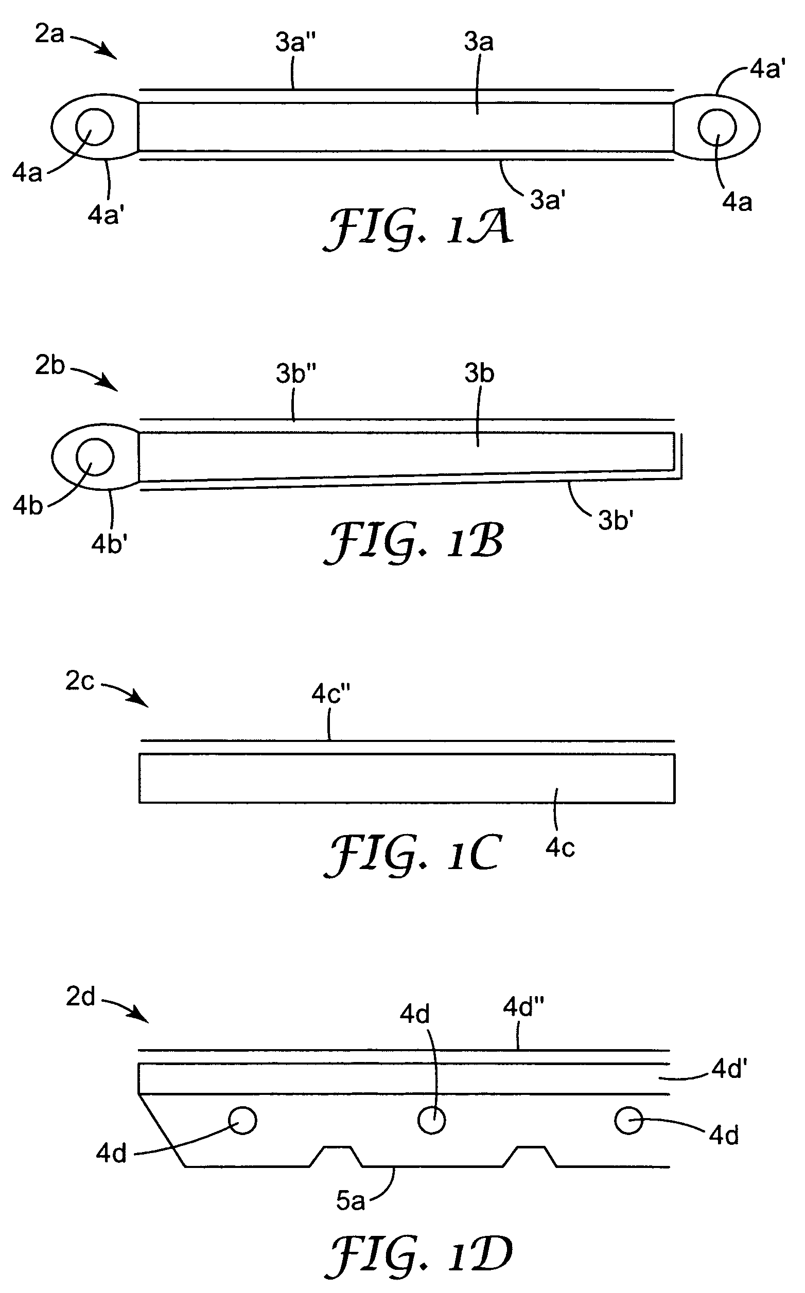
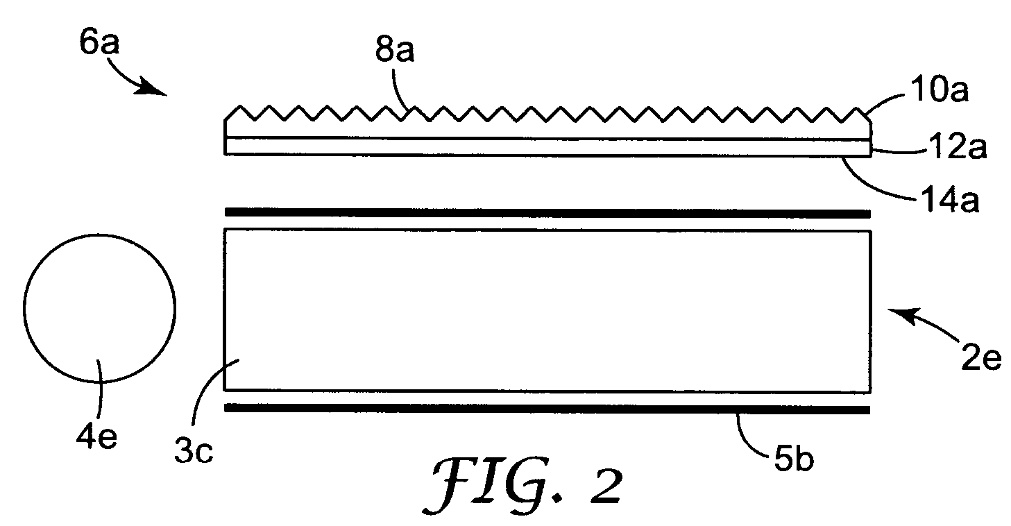
[0032]FIGS. 1A-1D show several examples of optical devices, such as backlights that may be used in LCDs. FIG. 1A shows a backlight 2a. The backlight 2a includes light sources 4a, such as one or more cold cathode fluorescent tubes (“CCFT”) or arrays of LEDs, that provide light from different sides or edges of the backlight, lamp reflectors 4a′ disposed about the light sources 4a, a lightguide 3a, which is illustrated as a substantially planar lightguide, a back reflector 3a′ and optical films 3a″, which may be any suitable optical films. FIG. 1B shows a backlight 2b including a light sour...
PUM
 Abstract
Description
Claims
Application Information