Gyro sensor of an electrostatic driving and capacitance detecting type

a capacitance detection and electrostatic driving technology, applied in the direction of acceleration measurement using interia forces, turn-sensitive devices, instruments, etc., can solve the problems of insufficient high voltage, inability to rapidly start self-excitation of the vibrator, and insufficient sensor output indicating a yaw ra

Inactive Publication Date: 2008-01-29
DENSO CORP
View PDF7 Cites 26 Cited by
  • Summary
  • Abstract
  • Description
  • Claims
  • Application Information

AI Technical Summary

Benefits of technology

[0014]Accordingly, because the starting circuit provides the start signal for the driving circuit as a boosting clock signal to generate the oscillation encouraging signal in the driving circuit, the self-excitation of the vibrator can be reliably and rapidly started in response to the oscillation encouraging signal of a boosted voltage.

Problems solved by technology

Therefore, a sensor output correctly indicating a yaw rate cannot be sufficiently obtained.
Therefore, the driving signal of the high voltage cannot be obtained until the self-excitation of the vibrator starts is started to generate the clock signal in a feedback loop of a sensor circuit, and the self-excitation of the vibrator cannot be rapidly started unless the driving signal of the high voltage is not rapidly obtained.

Method used


Image

  • Gyro sensor of an electrostatic driving and capacitance detecting type
  • Gyro sensor of an electrostatic driving and capacitance detecting type
  • Gyro sensor of an electrostatic driving and capacitance detecting type

Examples


embodiment 1

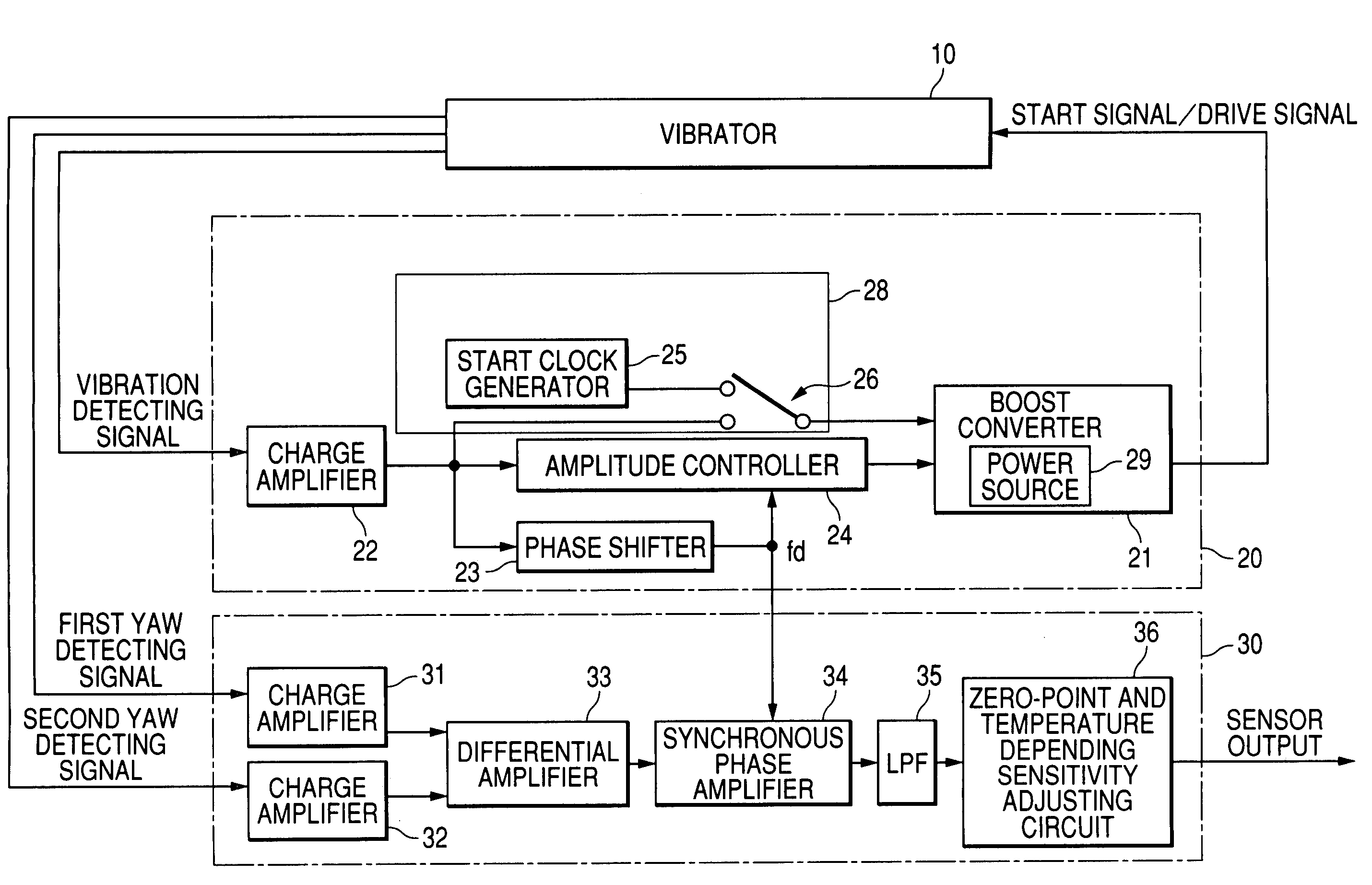
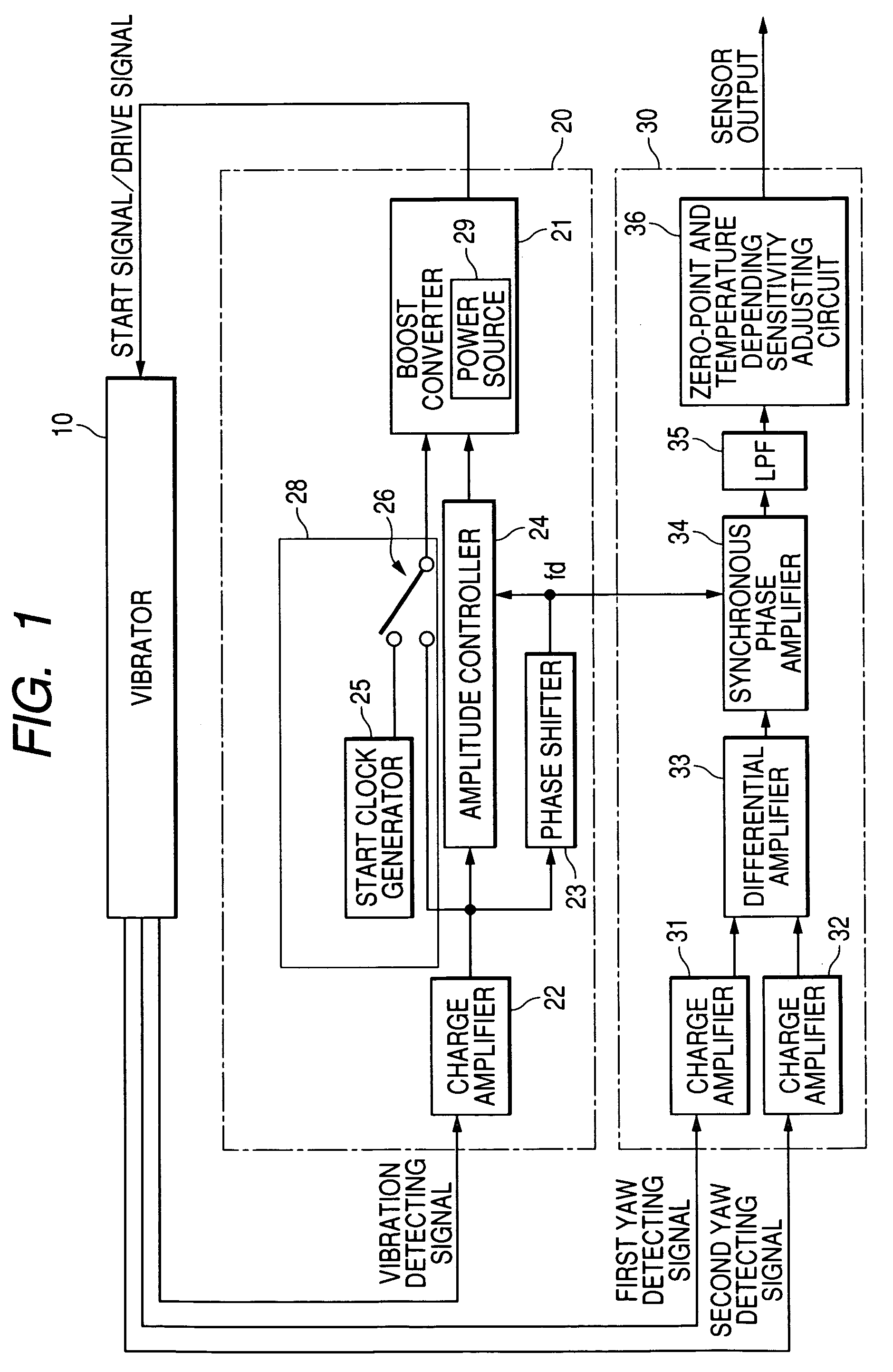
[0019]A gyro sensor of an electrostatic driving and capacitance detecting type is shown in FIG. 1 according to a first embodiment.

[0020]As shown in FIG. 1, a gyro sensor (or yaw rate sensor) disposed on a vehicle has a vibrator 10, a driving circuit 20, and a yaw detecting circuit 30. The vibrator 10 has a driving sensor element (not shown) and a pair of yaw detecting sensor elements (not shown). On condition that the driving sensor element is vibrated, the vibrator 10 outputs a vibration detecting signal to the circuit 20. When a yaw is added to the vibrator 10 during the vibration of the driving sensor element, the yaw detecting sensor elements are vibrated due to Corioli's force, and the yaw detecting sensor elements of the vibrator 10 output first and second yaw detecting signals to the circuit 30, respectively.

[0021]The circuit 20 generates a predetermined voltage, generates a control signal from the first detecting signal outputted from the vibrator 10, boosts the predetermine...

embodiment 2

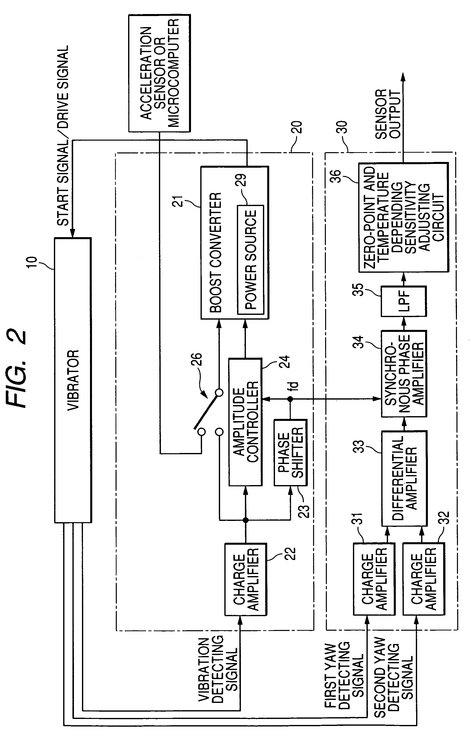
[0037]FIG. 3 is a block diagram of a gyro sensor according to a second embodiment of the present invention.

[0038]The sensor shown in FIG. 3 differs from that shown in FIG. 1 in that the sensor additionally has a monitor 27 in the vibration starting circuit 28. The monitor 27 detects or judges whether or not the self-excitation of the vibrator 10 is started. When the self-excitation of the vibrator 10 is started, the monitor 27 controls the switch 26 to change over from the connection of the converter 21 with the generator 25 to the connection of the converter 21 with the amplifier 22.

[0039]More specifically, the monitor 27 has a comparator for comparing a reference voltage Vref with a voltage of a vibration detecting signal outputted from the amplifier 22. The reference voltage Vref is preset such that the voltage of the detecting signal stably vibrated exceeds the voltage Vref. Therefore, when the self-excitation of the vibrator 10 is started, the voltage of the detecting signal ex...


PUM


Abstract

A gyro sensor having a vibrator and a start circuit generates an oscillation encouraging signal by boosting a first voltage to a voltage of the signal in response to a start signal of a start frequency sent from the start circuit. The vibrator is vibrated in response to the oscillation encouraging signal. When the vibrator is self-excited, the vibrator outputs a first detecting signal indicating an oscillating amplitude and oscillating frequency in the vibration of the vibrator. The sensor boosts the first voltage to a second voltage in response to the first detecting signal and generates a driving signal of a driving frequency and the second voltage. The self-excitation of the vibrator is continued in response to the driving signal. The vibrator outputs a second detecting signal indicating a yaw added to the vibrator. The sensor generates a sensor signal corresponding to the yaw from the second detecting signal.

Description

CROSS-REFERENCE TO RELATED APPLICATION[0001]This application is based upon and claims the benefit of priority of the prior Japanese Patent Application 2005-173710 filed on Jun. 14, 2005 so that the contents of which are incorporated herein by reference.BACKGROUND OF THE INVENTION[0002]1. Field of the Invention[0003]The present invention relates to a gyro sensor (or yaw rate sensor) wherein a physical quantity such as a yaw added to the sensor is detected based on a detecting signal transmitted from a vibrator when the vibrator is vibrated in self-excitation in response to a driving signal transmitted from the vibrator.[0004]2. Description of Related Art[0005]A conventional gyro sensor is, for example, installed in a vehicle to detect a yaw rate indicating an angular velocity of the vehicle. In this sensor, a feedback loop is formed by a vibrator and a driving circuit to self-excite the vibrator at its natural frequency, and a rate of yaw added to the vibrator is detected in a yaw de...

Claims


Application Information

Patent Timeline
Patent Type & Authority Patents(United States)
IPC IPC(8): G01P9/04G01C19/56G01C19/5776
CPCG01C19/56
Inventor KUTSUNA, YUJI
Owner DENSO CORP
Why Eureka
Try Eureka