Vehicle seat

a technology for vehicles and seats, applied in the field of vehicles seats, can solve the problems of air outlets being uncoupled from air holes, damaging the air blower,

Active Publication Date: 2008-01-29
TS TECH CO LTD
View PDF15 Cites 52 Cited by
  • Summary
  • Abstract
  • Description
  • Claims
  • Application Information

AI Technical Summary

Benefits of technology

[0018]Consequently, it is possible to obtain the vehicle seat which has a seat air conditioning function capable of ejecting comfortable air with high pressure, comfortable to sit in, and is further easy to be manufactured.
[0023]According to the vehicle seat, by integrally forming the insert member with the seat pad, embedding operation of the insert member to the inside of the air hole can be eliminated, enabling to simplify the manufacturing process of the vehicle seat. Moreover, the insert member can be fixed to the seat pad more firmly.
[0025]According to the vehicle seat, providing the bellows structure in the duct can make it possible to deform the duct to flexibly correspond to the deformation of the seat cushion and the seat back, which makes the air outlet not easily uncoupled from the air hole.
[0033]As described above, in the case of providing two or more bellows structures between the two consecutive air outlets, the portion between the two bellows structures of the duct inclines and rotates corresponding to the relative position change of the two air outlets accompanying the deformation of the seat back. However, the portion between the air outlet and the bellows structure does not incline and rotate. That is, the relative position change of the two air outlets is absorbed at the portion between the two bellows structures, so that the action of the external force acting to the air outlets to uncouple the air outlets from the air holes can be decreased, thus enabling to obtain the effect to increase the bonding strength of the air outlet to the air hole.
[0041]According to the vehicle seat, by integrally forming the insert member with the seat pad, embedding operation of the insert member to the inside of the air hole can be eliminated, enabling to simplify the manufacturing process of the vehicle seat. Moreover, the insert member can be fixed to the seat pad more firmly.
[0048]According to the vehicle seat, since a portion of each duct attached to the seat cushion side and the seat back side bends upward or downward with respect to the horizontal direction. Thus, for example, when a passenger spills liquid such as a drink or the like on the seat cushion or the seat back, the liquid entered from the air holes into the ducts is prevented from flowing at the upwardly bending portion of the duct, or stays at the downwardly bending portion of the duct. Thus, the situation of the air blower failure due to the liquid reached to the air blowers can be prevented from occurring.

Problems solved by technology

Thus, when the amount of the deformation of the seat cushion and the like is large, the air outlets may be uncoupled from the air holes.
Accordingly, for example, when a passenger spills liquid such as a drink or the like, the liquid entered from the air holes may pass the inside of the air exhaust duct to reach the air blower, thereby damaging the air blower.

Method used


Image

  • Vehicle seat
  • Vehicle seat
  • Vehicle seat

Examples


first embodiment

[0072]The first embodiment for embodying the present invention will be explained in detail below referring to the drawings.

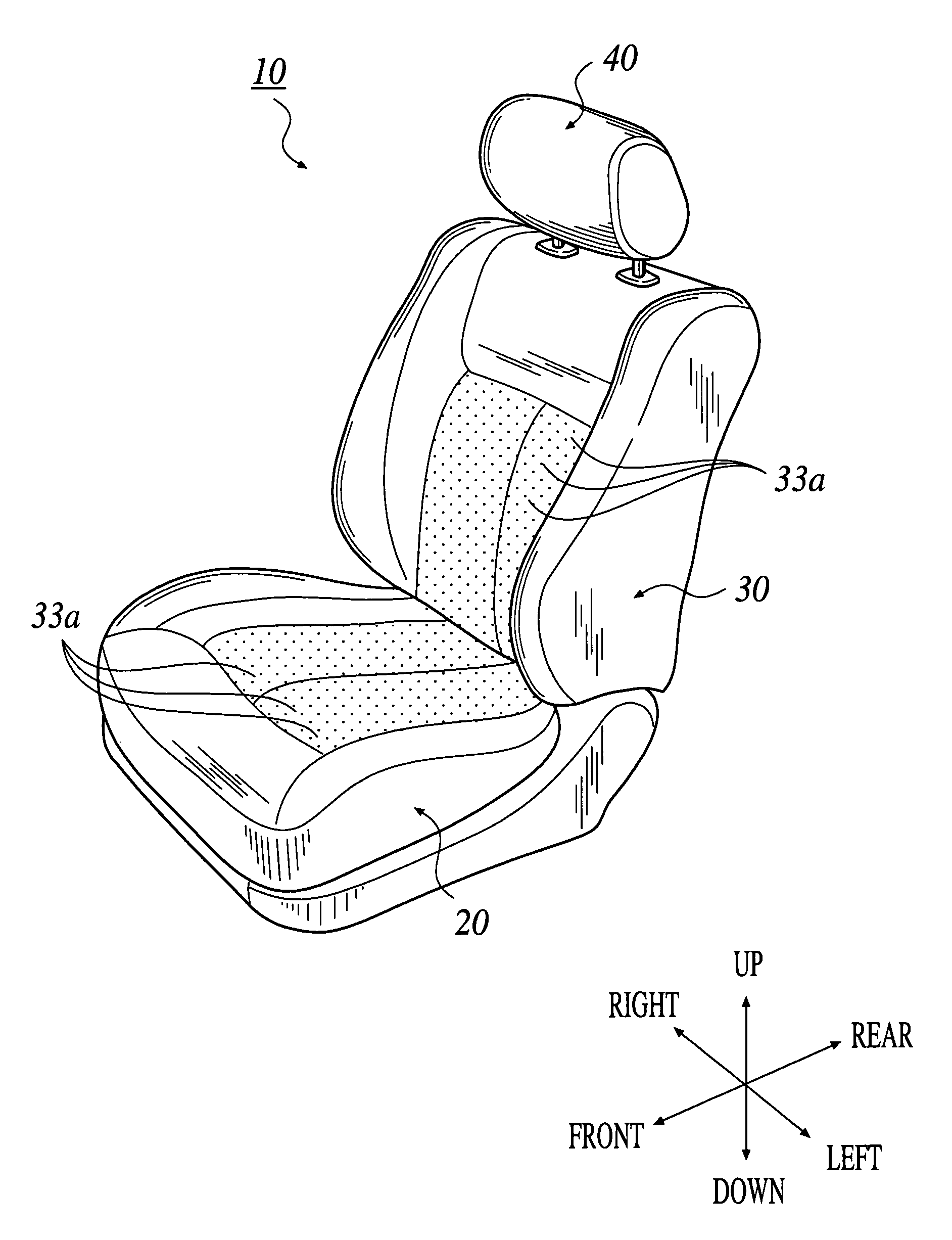
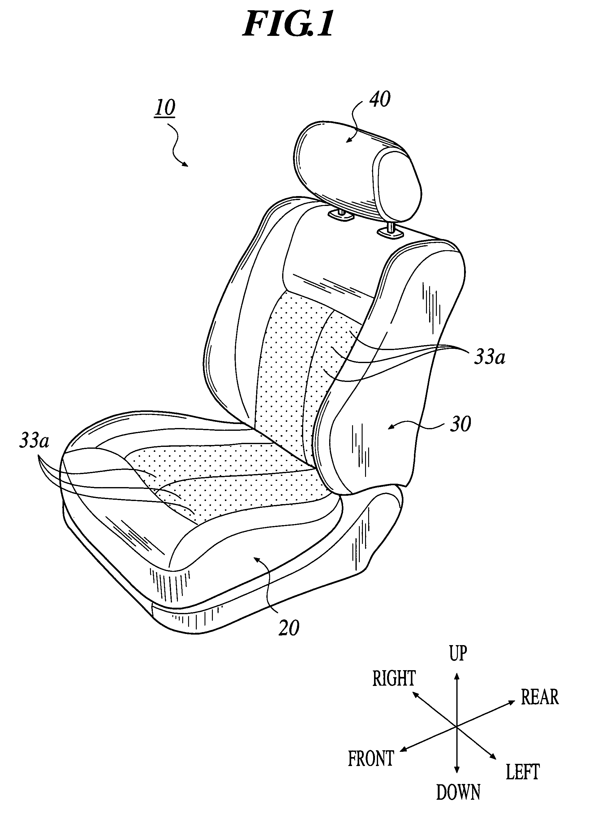
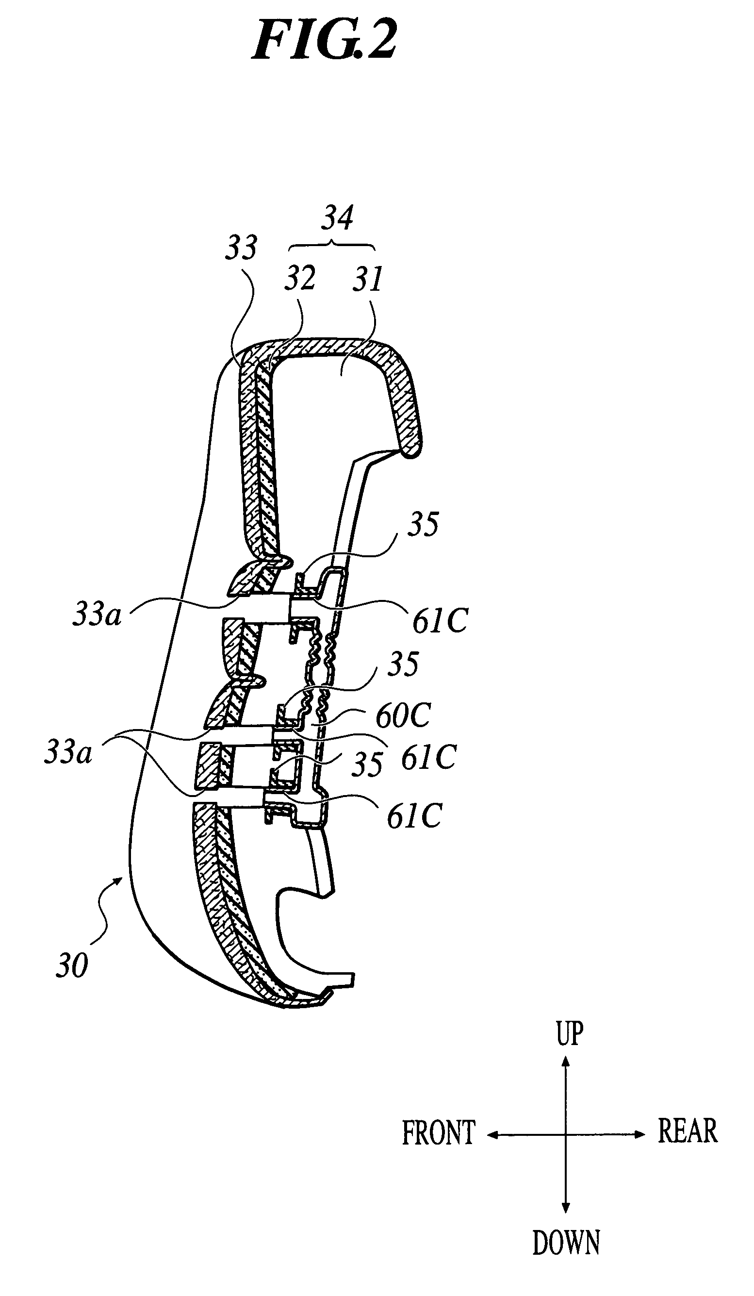
[0073]As shown in FIG. 1, a vehicle seat 10 is schematically configured to comprise a seat cushion 20, a seat back 30, a head rest 40 provided on the upper portion of the seat back 30 and the like. Among them, as shown in FIG. 2, the seat back 30 is configured such that a surface of a pad 31 which keeps a seat shape and functions as a cushion member is covered with a cover pad 32 with permeability, and the surface of the cover pad 32 is further covered with a top cover member 33. FIG. 2 shows the seat back 30, however, similarly, the seat cushion 20 is also configured such that the surface of the pad 31 is covered with the cover pad 32 and the top cover member 33. Hereinafter, the combination of the pad 31 and the cover pad 32 is described as a “seat pad 34”.

[0074]As shown in FIG. 1, there are a plurality of air holes 33a formed in the surface of the top cover m...

second embodiment

[0092]The second embodiment for embodying the present invention will be explained in detail below referring to the drawings.

[0093]As shown in FIG. 7, a vehicle seat 110 is schematically configured to comprise a seat cushion 120, a seat back 130, a head rest 140 provided on the upper portion of the seat back 130 and the like. Among them, as shown in FIG. 8, the seat back 130 is configured such that a surface of a pad 131 which keeps a seat shape and functions as a cushion member is covered with a cover pad 132 with permeability, and the surface of the cover pad 132 is further covered with a top cover member 133. FIG. 8 shows the seat back 130, however, similarly, the seat cushion 120 is also configured such that the surface of the pad 131 is covered with the cover pad 132 and the top cover member 133. Hereinafter, the combination of the pad 131 and the cover pad 132 is described as a “seat pad 134”.

[0094]As shown in FIG. 7, there are a plurality of air holes 133a formed in the surfac...

third embodiment

[0114]The third embodiment for embodying the present invention will be explained in detail below referring to the drawings.

[0115]As shown in FIG. 15, a vehicle seat 210 is schematically configured to comprise a seat cushion 220, a seat back 230, a head rest 240 provided on the upper portion of the seat back 230 and the like. Among them, as shown in FIG. 16, the seat back 230 is configured such that a surface of a pad 231 which keeps a seat shape and functions as a cushion member is covered with a cover pad 232 with permeability, and the surface of the cover pad 232 is further covered with a top cover member 233. FIG. 16 shows the seat back 230, however, similarly, the seat cushion 220 is also configured such that the surface of the pad 231 is covered with the cover pad 232 and the top cover member 233. Hereinafter, the combination of the pad 231 and the cover pad 232 is described as a “seat pad 234”.

[0116]There is a plurality of air holes 233a formed in the surface of the top cover ...


PUM


Abstract

A vehicle seat having: a seat cushion and a seat back formed by covering a surface of a seat pad with a top cover member; a plurality of air holes which penetrate the seat pad to reach a surface of the top cover member; a plurality of air outlets which project from a surface of a duct to be connected to the air holes; and an air blower to pressure and feed air inside a vehicle compartment to the air holes through the duct and the air outlets, wherein an engagement portion which projects in a radial direction of one of the air outlets is provided at a tip of the one of the air outlets.

Description

BACKGROUND OF THE INVENTION[0001]1. Field of the Invention[0002]The present invention relates to a vehicle seat having an air conditioning function.[0003]2. Description of the Related Art[0004]Recently, there is known a vehicle seat having an air conditioning function in which a plurality of air holes are provided in a top cover member of a seat cushion and a seat back of the vehicle seat, and air from an air blower is ejected from the air holes (refer to JP-Tokukaihei-10-297274).[0005]The vehicle seat disclosed in JP-Tokukaihei-10-297274 is schematically configured such that the plurality of air holes are provided to penetrate a top cover member, a cover pad and a pad forming the seat cushion and the seat back, an air blower, an intermediate duct and a seat cushion air exhaust duct are arranged on a lower surface of the seat cushion, and a seat back air exhaust duct is arranged on a back surface of the seat back.[0006]A plurality of air outlets which slightly project from the surfa...

Claims


Application Information

Patent Timeline
Patent Type & Authority Patents(United States)
IPC IPC(8): A47C7/72A47C7/02A47C7/74B60H1/00B60N2/56
CPCB60N2/5621B60N2/5635B60N2/7017
Inventor ISHIMA, SHINYANAGAYAMA, MASAKI
Owner TS TECH CO LTD
Why Eureka
Try Eureka