Multichip LED lighting device

a multi-chip led lighting and LED technology, applied in the direction of lighting support devices, electrical apparatus casings/cabinets/drawers, coupling device connections, etc., can solve the problems of premature deterioration of led bare chips, significantly longer life expectancy, and differing specifications of replacement led modules from those of original led modules, so as to improve workability and efficiency, the effect of efficient heat expulsion

Active Publication Date: 2008-01-29
PANASONIC CORP
View PDF25 Cites 190 Cited by
  • Summary
  • Abstract
  • Description
  • Claims
  • Application Information

AI Technical Summary

Benefits of technology

[0014]In view of the stated problems, the object of the present invention is to provide a lighting device in which stability of luminous intensity of an LED bare chip in an LED module is improved, and in which the LED module can be easily replaced or expanded in number with an LED module of differing specifications.

Problems solved by technology

In an LED lighting device with such a structure, the LED bare chips exhibit premature deterioration due to the heat generated by the LED bare chips themselves during operation.
However, a problem arises that the specifications of the replacement LED module differ from those of the original LED module.
Specifically, LEDs have a significantly longer life expectancy than conventional incandescent lamps, and with rapid progress in the development of LEDs, it is unlikely that the specifications (for example the Vf of the LED bare chips) of LED modules at the time of replacement will be the same as the specifications when the lighting device was designed.
This is not ideal for the LED modules.
In the same way, if a dependant LED module is replaced, the capability of the replacement dependant module will suffer.
In this way, according to the aforementioned patent document, it is difficult to obtain maximum performance from each LED module because it is not possible to compensate for differences in LED performance of the LED modules.
Furthermore, an LED module cannot be replaced with the most current LED module that is superior in aspects such as Vf of the LED bare chip.

Method used


Image

  • Multichip LED lighting device
  • Multichip LED lighting device
  • Multichip LED lighting device

Examples


first example

1. FIRST EXAMPLE

[0136]The following describes, as the LED bare chip abnormality, the LED module exhibiting an excessive rise in temperature, with use of FIGS. 11 to 13.

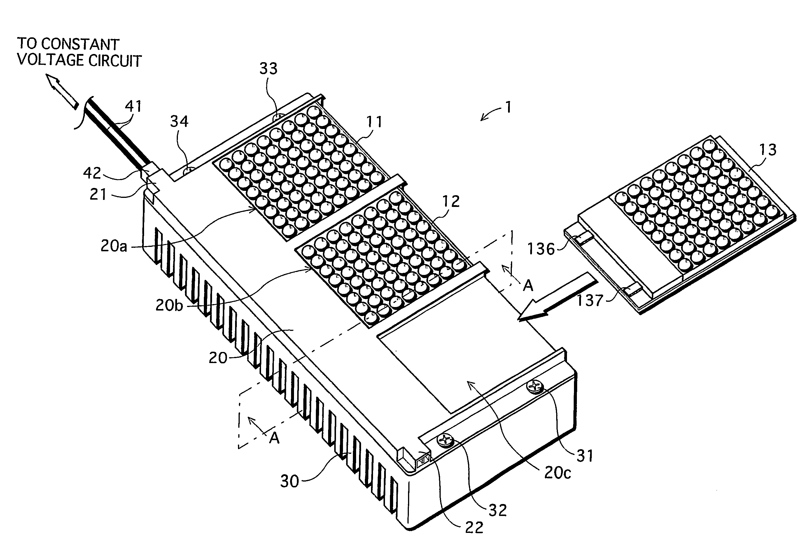
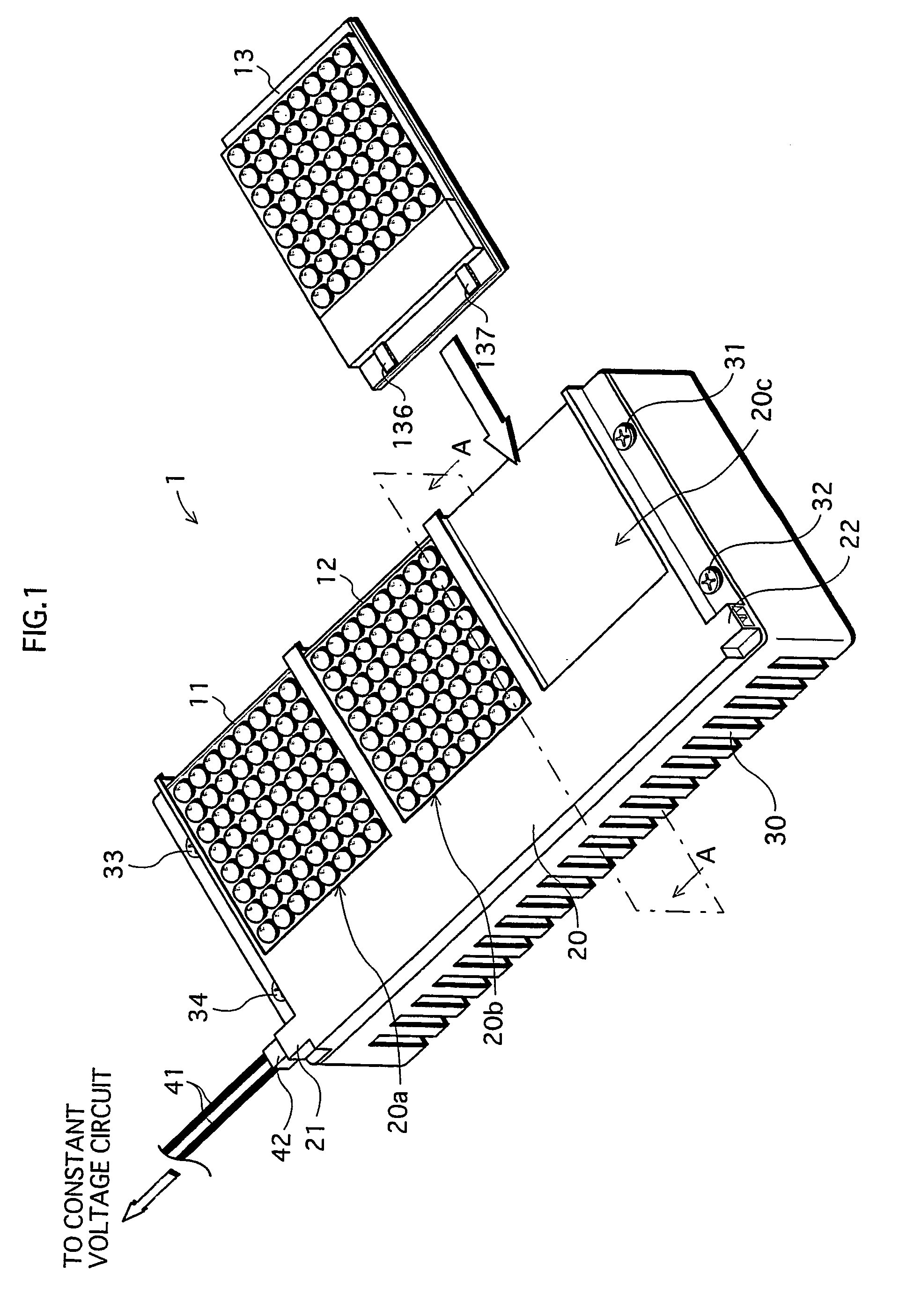
[0137]As shown in FIG. 11, a lighting device 101 of the fifth modification includes a module socket 120 that has three detachable LED modules 18, 19 and 20, and a constant voltage circuit unit 140 that provides a constant voltage to the LED modules 18, 19 and 20. Note that the constant voltage circuit unit 140 and the module socket 120 are connected by three leads.

[0138]Each of the LED modules 18, 19 and 20 has substantially the same structure, and the following describes the structure of the LED module 18.

[0139]As shown in FIGS. 11 and 12, the LED module 18 has a constant current circuit unit 18a, an LED mounting unit 18b, and a thermal element 18c. Note that since the constant current circuit unit 18a and the LED mounting unit 18b are as described in the preferred embodiment, a description thereof is omitted here.

[0...

second example

2. SECOND EXAMPLE

[0177]The following describes with use of FIG. 14 a case in which the amount of current in the LED bare chips increases excessively, as an example of an abnormality in the LED bare chips. Note that the module socket and constant voltage circuit unit of the present example are the same as those in the first example, and therefore descriptions thereof are omitted. Furthermore, since each of the LED modules in the present example has the same structure, the following describes an LED module 21.

[0178]The LED module 21 includes a constant current circuit unit 21a, an LED mounting unit 21b and a current detection unit 21c, as shown in FIG. 14. Note that the constant current circuit unit 21a and the LED mounting unit 21b are as described in the preferred embodiment, and therefore not described here.

[0179]The current detection unit 21c is for detecting current abnormalities in the LED mounting unit 18b (the current detection unit is the abnormality detection unit of the pre...


PUM


Abstract

In a module socket, a connecter and a connector are connected by wiring, and three LED modules are connected in parallel with respect to a constant voltage circuit unit via the wiring. Each module has a constant current circuit unit and an LED mounting unit. The constant current circuit unit includes one resistor and two transistors mounted on a surface of a sub-substrate on which a conductive land is formed. The sub-substrate is bonded to a main substrate.

Description

TECHNICAL FIELD[0001]The present invention relates to a lighting device, and in particular to a lighting device in which light emitting diodes are used as a light source.BACKGROUND ART[0002]In recent years lighting devices that use light emitting diodes (hereinafter referred to as “LED(s)”) have been under development, and some are being put into practical use.[0003]One example of a lighting device that uses LEDs (hereinafter referred to as an “LED lighting device”) is one in which LED bare chips are mounted on a substrate (this arrangement is called an “LED module”), an the LED bare chips are made to emit light according to power from a power supply source. A plurality of LED bare chips are generally mounted on the substrate because sufficient light to produce a lighting device is not provided by only one LED bare chip. The LED bare chips are mounted densely in order to produce a more compact lighting device.[0004]In an LED lighting device with such a structure, the LED bare chips ...

Claims


Application Information

Patent Timeline
Patent Type & Authority Patents(United States)
IPC IPC(8): F21V23/04F21V21/00H05B37/02H01R33/00F21V19/04B60Q1/00F21V29/00H01L33/00H01L33/48H01L33/54H01L33/56H05B44/00
CPCH05B33/0803H05B33/0815H05B33/0854H05B33/089H05B33/0827F21V19/04F21V29/004F21Y2101/02Y10S362/80F21V23/003F21Y2105/001F21Y2105/10F21Y2115/10F21V23/006H05B45/46F21V29/70H05B45/56H05B45/325H05B45/395H05B45/18
Inventor SETOMOTO, TATSUMIMATSUI, NOBUYUKITAMURA, TETSUSHITANIMOTO, NORIYASUSHIMIZU, MASANORI
Owner PANASONIC CORP
Why Eureka
Try Eureka