
Reamer with clamping arrangement for adjusting cutting insert and other cutting tools with clamping arrangements for adjusting cutting inserts

a technology of clamping arrangement and cutting insert, which is applied in the field of cutting tools, can solve the problems of limited boring tolerance, machining tolerance, and tool development toward this objective can only be combined to a limited extent, and achieve the effect of preventing an overloading of the screw connection

Inactive Publication Date: 2008-01-29
KENNAMETAL INC
View PDF16 Cites 19 Cited by
  • Summary
  • Abstract
  • Description
  • Claims
  • Application Information

AI Technical Summary

Benefits of technology

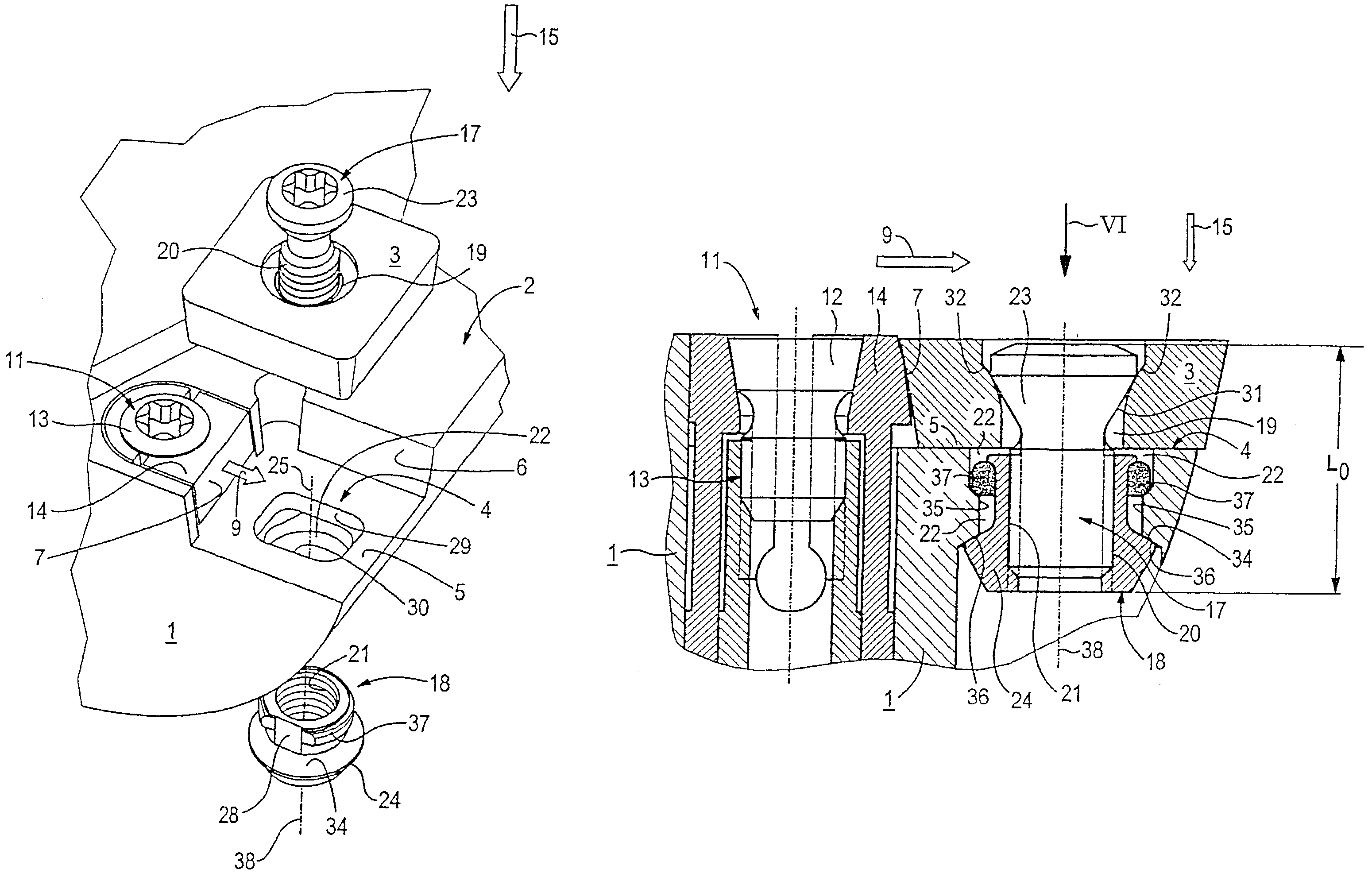
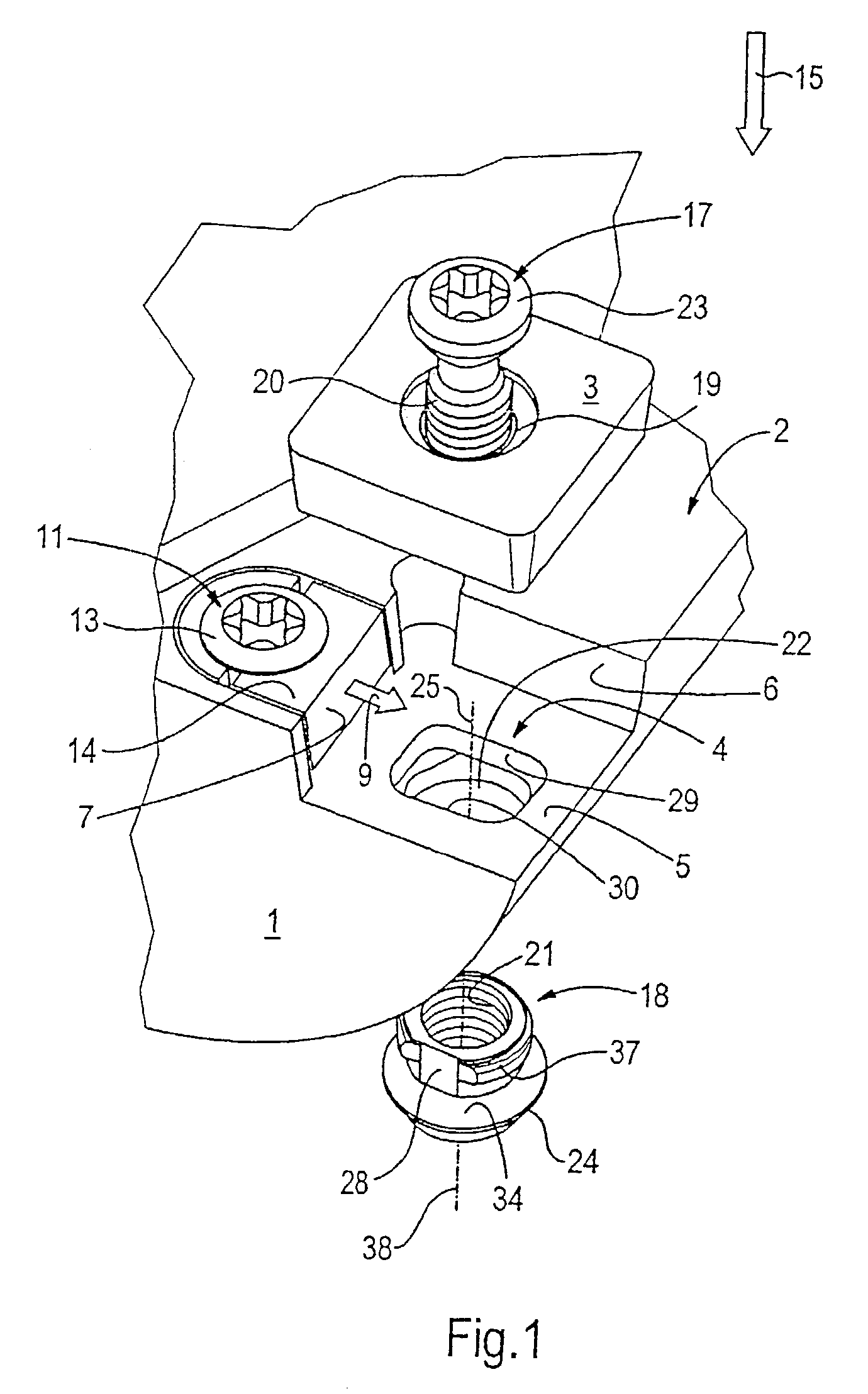
[0008]This object is accomplished by a cutting tool with a tool shank (1) which supports a cutting insert in the form of a perforated plate (3), in particular a disposable perforated plate made of a hard cutting material, e.g. tungsten carbide or oxide ceramic, with a feed device (11) that acts transverse to the axis (10) of the hole in the feed direction (9) on the perforated plate (3) as an adjustment means for the positioning of the perforated plate (3) on the tool shank (1), and with a screw (17) that projects through the plate hole (19) of the perforated plate and with its screw head (23) braces the perforated plate (3) against a contact surface (5) on the tool shank (1) and, projecting through a bolt hole (22) of the tool shank (1), is engaged with its screw thread (20) in the nut thread (21) of a retaining lock nut (18), which retaining lock nut (18) is supported on the side facing away from the perforated plate seat (4) against the screw pressure (15) and so that it cannot rotate around the screw axis (10) on the tool shank, whereby the mutual stop surfaces of the screw head (23) and the perforated plate (3) on the one hand and of the retaining lock nut (18) and tool shank (1) on the other hand, as a result of their shapes, permit a mobility that follows the feed movement, in particular a rotational mobility of the screw fastener means that are fastened to each other (screw 17; retaining lock nut 18) with respect to the tool shank (1) and with respect to the perforated plate (3). Instead of an internal thread applied directly in the tool shank or instead of a movable, guided, sled-like mounting of the internal thread, this solution works with a retaining lock nut that is mounted so that it can to a certain extent float in the tool shank underneath the plate seat. The resulting floating mounting of the unit that consists of the nut and the inserted screw, which unit forms the screw bracing means, makes possible an automatic adjustment of the positioning and orientation of the screw thread axis relative to the axis of the perforated plate and to the axis of the bolt hole in the tool shank. The feed motion, which also allows a partial swiveling and / or rotation, occurs approximately in a plane that is defined by the screw thread axis, the orientation of which is variable, and by the feed direction that runs transverse to it.
[0009]One development of the object of the invention provides flexibility in the positioning of the backstop in and / or opposite to the feed direction. If the adjustable lateral stop surface is displaced toward the perforated plate, the retaining lock nut follows the adjustment movement opposite to the spring pressure. The purpose is to counteract an additional bending load of the screw caused by the adjustment movement. When the stop surface is retracted and when the perforated plate is replaced, the result is an automatic resetting or reverse pivoting of the retaining lock nut into its initial position.

Problems solved by technology

On the other hand, the tolerances of the width of the perforated plate and the position of the contact surfaces in the plate seat of the tool shank limit the machining tolerances of the cutting tool, which means that on a boring tool in particular, the boring tolerance is likewise limited.
However, tool developments toward this objective can only be combined to a limited extent with the advantages of the screw bracing of a perforated plate.
As the feed travel increases, the screw is subjected to an increasing bending load.
This bending load represents a safety risk that can cause not only damage to the tool, the workpiece and the machine, but can also pose a threat to the operating personnel.
However, this solution weakens the substructure of the perforated plate seat and deforms the substructure when the perforated plate is braced.

Method used


Image

  • Reamer with clamping arrangement for adjusting cutting insert and other cutting tools with clamping arrangements for adjusting cutting inserts
  • Reamer with clamping arrangement for adjusting cutting insert and other cutting tools with clamping arrangements for adjusting cutting inserts
  • Reamer with clamping arrangement for adjusting cutting insert and other cutting tools with clamping arrangements for adjusting cutting inserts

Examples


Embodiment Construction

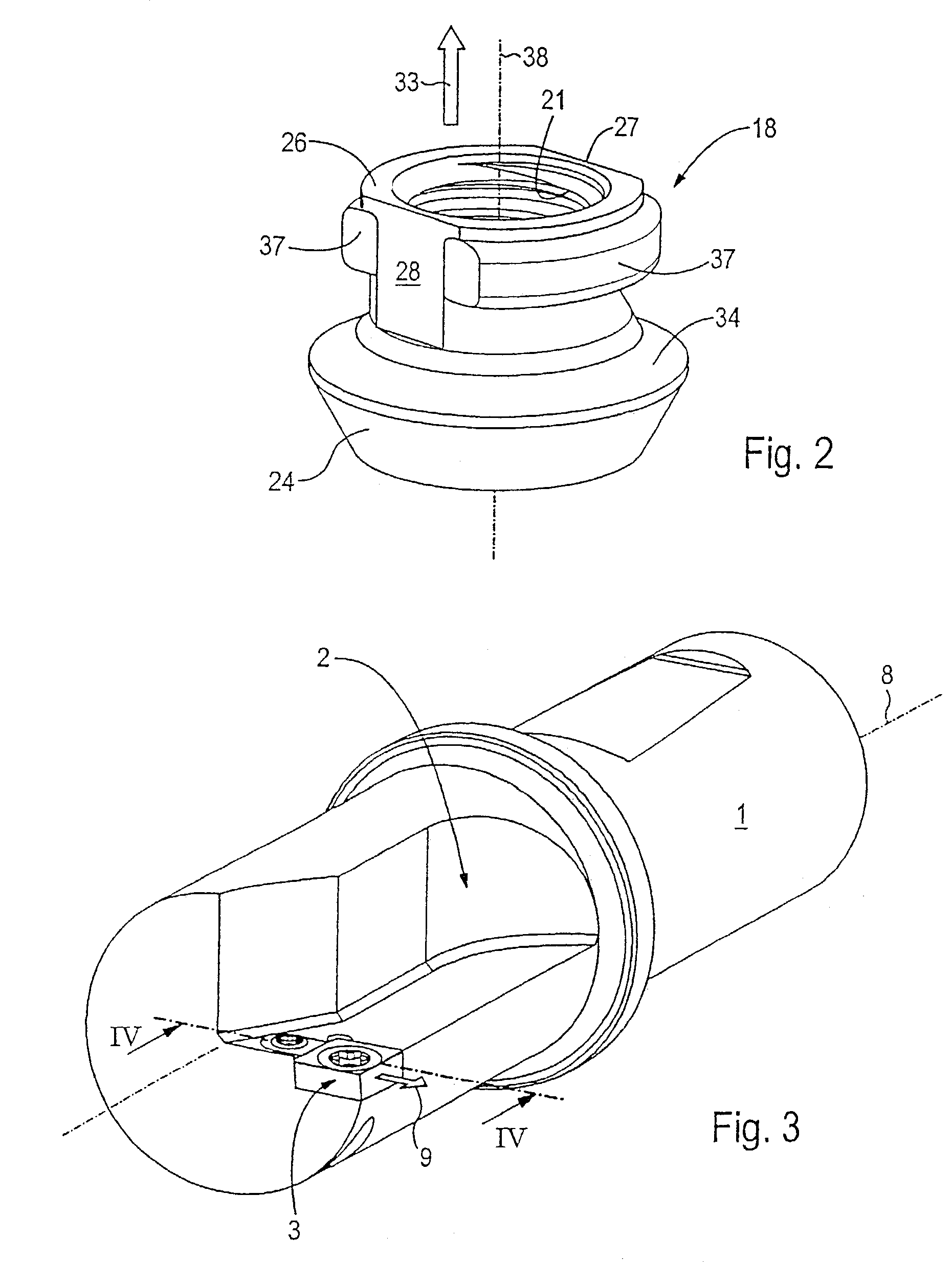
[0022]The drilling tool (FIG. 3) contains essentially the tool shank 1 and, braced in it, a perforated plate 3 made of tungsten carbide metal or oxide ceramic material. The perforated plate 3 is braced inside the plate seat 4 provided in a shank recess 2 on the tool shank 1 (FIG. 1). The plate seat.4 contains a contact surface 5 and two lateral stop surfaces 6 and 7 for the precise positioning of the perforated plate 3. The lateral stop surface 6 thereby runs approximately perpendicular and the lateral stop surface 7 runs approximately parallel to the axis of rotation 8 of the tool shank 1.

[0023]The lateral stop surface 7 which is approximately parallel to the axis of rotation 8 can be adjusted in the feed direction 9 with respect to the tool shank 1. The feed direction 9 runs approximately perpendicular to the axis of rotation 8 of the tool shank 1 and to the hole axis 10 of the perforated plate 3. The primary purpose of the feed is to adjust the radial position of the perforated p...


PUM

PropertyMeasurementUnit
pressureaaaaaaaaaa
diameteraaaaaaaaaa
surface areaaaaaaaaaaa

Abstract

A cutting tool with a cutting insert and a pivotable screw and nut combination for holding the cutting insert. The cutting tool also has a feed mechanism to adjust the position of at least one cutting edge of the cutting insert in the cutting tool.

Description

CONTINUING APPLICATION DATA[0001]This application is a Continuation-In-Part application of International Patent Application No. PCT / EP01 / 10945, filed on Sep. 21, 2001, which claims priority from Federal Republic of Germany Patent Application No. 100 47 079.3, filed on Sep. 22, 2000. International Patent Application No. PCT / EP01 / 10945 was pending as of the filing date of this application. The United States was an elected state in International Patent Application No. PCT / EP01 / 10945.BACKGROUND OF THE INVENTION[0002]1. Field of the Invention[0003]This invention relates to a cutting tool that can be realized in particular in the form of a rotary tool with a tool shank which acts as a support for a cutting insert in the form of a perforated plate, in particular a disposable perforated plate, and with a feed device as a means of adjustment for the positioning of the perforated plate on the tool shank. Stress applied by a simple screw is increasingly being used to fasten perforated plates o...

Claims


Application Information

Patent Timeline
Patent Type & Authority Patents(United States)
IPC IPC(8): B23B29/02B23B29/034B23B27/16B23C5/24
CPCB23B27/1655B23C5/2493B23B2200/3618B23B2205/04B23B2205/125B23B2240/04Y10T408/858Y10S408/713Y10T407/1936Y10T408/8593Y10T408/9098B23B27/16
Inventor JAGER, HORSTZEUG, BERTHOLD
Owner KENNAMETAL INC
Learn More