Wave energy converters (WECs) with linear electric generators (LEGs)

a technology of linear electric generators and wave energy converters, which is applied in the direction of electric generator control, machines/engines, mechanical equipment, etc., can solve the problems of inefficiency of devices and systems employing them, performance, cost, reliability and/or survivability limitations of known wave energy conversion systems utilizing linear electric generators, etc., to avoid the constraining of the range of motion of the moving shell, reduce the effect of impact load and good and efficient coupling

Active Publication Date: 2008-01-29
OCEAN POWER TECHNOLOGIES
View PDF47 Cites 108 Cited by
  • Summary
  • Abstract
  • Description
  • Claims
  • Application Information

AI Technical Summary

Benefits of technology

[0009]A wave energy converter (WEC) system embodying the invention includes a power take-off (PTO) device that directly converts mechanical energy into electric energy and mitigates and / or avoids the problems listed above.

Problems solved by technology

These devices and the systems employing them tend to be inefficient, expensive to make and difficult to design for survivability.
However, known wave energy conversion systems utilizing linear electric generators have performance, cost, reliability and / or survivability limitations resulting from the configuration and / or the suggested type of linear electric generator.
Deficiencies of existing wave energy conversion systems utilizing known linear electric generators include the following:1. known linear electric generators have limited stroke or range of motion, limiting the amount of power that can be extracted, resulting in complex, expensive mechanical designs to limit the range of force applied to the power take-off device, and / or decreasing the survivability of the wave energy converter systems; and / or2. in known linear electric generator systems, induction coils are an integral part of the shell or column (e.g. induction coils encircle one of the wave energy converter structural elements), resulting in complex and expensive mechanical designs; and / or3. known linear electric generator magnet and induction coil assemblies must be housed together in a watertight enclosure, necessitating unreliable and / or expensive sealing devices at an air / water interface.

Method used


Image

  • Wave energy converters (WECs) with linear electric generators (LEGs)
  • Wave energy converters (WECs) with linear electric generators (LEGs)
  • Wave energy converters (WECs) with linear electric generators (LEGs)

Examples


Embodiment Construction

I. Systems Suitable for Practicing the Invention;

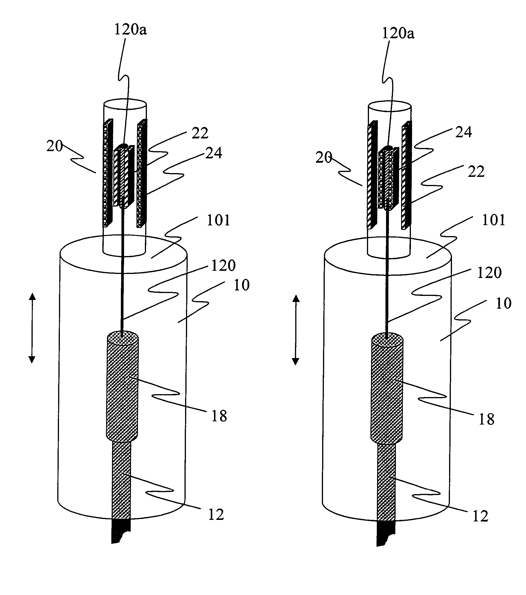
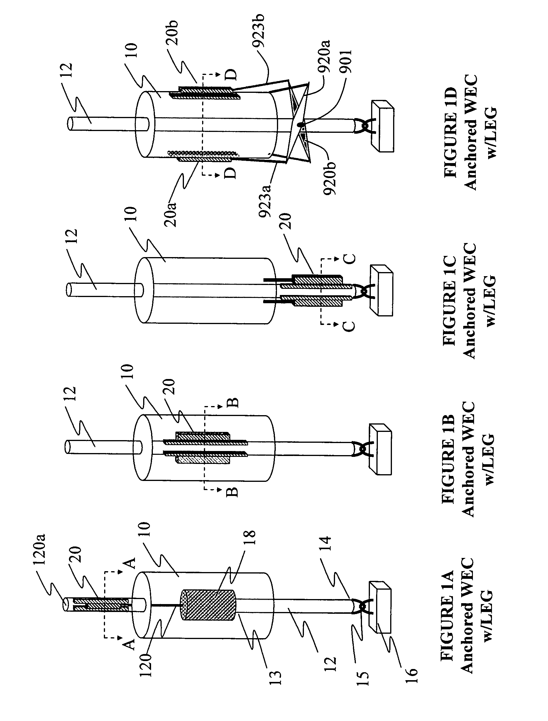
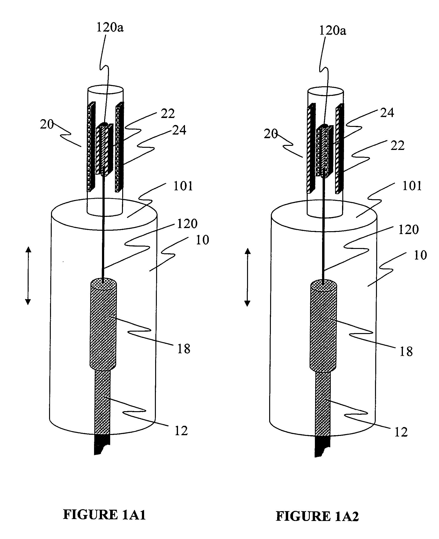
[0059]Wave energy converters (WECs) suitable for practicing the invention may include systems of the type shown in FIGS. 6A, 6B, and 6C. FIG. 6A shows a neutrally buoyant shell 10 typically submerged below the surface of the ocean with a tethered or anchored vertical column (spar) 12. FIG. 6B shows a buoyant shell typically floating at the surface of the ocean also with a tethered or anchored vertical column (spar) 12. FIG. 6C illustrates a dual wave energy absorber where the shell 10 and the spar 12 move relative to each other, the shell generally in phase with the waves and the spar tending to move out of phase with the shell and / or the ocean waves. Each one of the WECs shown in FIGS. 6A, 6B and 6C may include one, or more, power take off (PTO) which includes a linear electric generator (LEG) device 20 connected between the “shell” and the “spar”.

[0060]In general, any WEC which includes first and second structures (e.g., a shell and...


PUM


Abstract

An ocean wave energy converter (WEC) utilizes the relative motion between permanent magnet and induction coil assemblies to generate electricity. The permanent magnet assemblies and induction coil assemblies are separately housed in watertight enclosures, enabling a wide range of wave energy converter configurations, nearly unlimited stroke and obviating the need for a common magnet / coil enclosure with seals. The magnet assemblies are constructed with surface or buried magnets. The wave motion moves a magnet assembly relative to a stationary coil assembly, or vice versa. Either the magnet assembly or the induction coil assembly are made long enough to provide the generation of electricity over a desired operational range of travel. Various means are provided to maintain the spacing (“gap”) between the magnetic and coil assemblies relatively constant.

Description

CROSS REFERENCES TO RELATED APPLICATIONS[0001]This application claims priority from provisional patent application Ser. No. 60 / 553,666 titled Wave Energy Converters (WECs) with Linear Electric Generators (LEGs) filed Mar. 16, 2004, the teachings of which are incorporated herein by reference.BACKGROUND OF THE INVENTION[0002]This invention relates to apparatus, systems and methods for converting energy present in ocean surface waves into electric energy.[0003]A known system for capturing ocean surface wave energy includes: (a) a first structure (which may be or interchangeably referred to herein as a “shell” or “vessel” or “float”) which, when placed in a body of water, is designed to move up and down, generally, in phase with the waves in the water and thus absorb and / or release energy; (b) a second structure (which may be or interchangeably referred to herein as a “shaft”, “spar”, “column” or piston) which is either stationary or moves generally out of phase relative to the waves an...

Claims


Application Information

Patent Timeline
Patent Type & Authority Patents(United States)
IPC IPC(8): F03B13/12F03B13/10H02P9/04
CPCF03B13/1895H02K35/02H02K35/04F05B2220/7066Y02E10/38F05B2220/707Y02E10/30
Inventor TAYLOR, GEORGE W.STEWART, DAVID B.
Owner OCEAN POWER TECHNOLOGIES
Why Eureka
Try Eureka