Wind turbine

a wind turbine and turbine technology, applied in the field of turbines, can solve the problems of large bounce back of wind energy, and large loss of wind energy, and achieve the effect of maximizing the efficiency of the wind turbin

Inactive Publication Date: 2008-01-29
SOHN CHESTER
View PDF14 Cites 92 Cited by
  • Summary
  • Abstract
  • Description
  • Claims
  • Application Information

AI Technical Summary

Benefits of technology

[0010]A main object of the present invention is to provide a wind turbine which comprises a rotor hub having a peripheral guiding rim adapted for guiding a flow of air to a plurality of blades for maximizing an efficiency of the wind turbine.
[0011]Another object of the present invention is to provide a wind turbine, wherein the rotor hub has an air passageway for allowing air to pass therethrough, so as minimize the air drag affecting the wind turbine, and enhance the efficiency thereof.
[0012]Another object of the present invention is to provide a wind turbine, wherein each of the plurality of blades is shaped and sized to facilitate guiding of air flow from the hub to the blade, so as to maximize the amount of air flow which can be guided from the hub to the blade for maximizing conversion of the wind's kinetic energy to the blades' rotational power.
[0013]Another object of the present invention is to provide a wind turbine which can be utilized in a wide variety of circumstances so as to facilitate widespread application of the present invention.
[0016]a plurality of blades outwardly and spacedly extended from the guiding rim of the rotor hub, wherein each of the blades has a blade surface arranged in such a manner that when the air flow exerts on the blade surfaces of the blades, the rotor hub is driven to rotate for generating the rotational power to the power generator, wherein the rotor hub allows the air flow passing through the air passageway to minimize an air drag thereof so as to enhance an efficiency of the rotational power generated by the rotor hub.

Problems solved by technology

A major problem for this kind of conventional wind turbine is that when air flows through the turbine, a substantial portion of which will be bounced back by the hub.
As a result, that portion does not contribute to the rotational movement of the turbine.
At a given time, much energy which is carried by wind will be lost simply by it not being properly collected.
What is worse is that if the energy carried by that portion of wind which impinges on the turbine but is not properly converted into kinetic energy of the hub and the blade, the excess energy will actually cause air drag and retard the rotational movement of the wind turbine, thereby significantly reducing an efficiency thereof.

Method used


Image

  • Wind turbine
  • Wind turbine
  • Wind turbine

Examples


Embodiment Construction

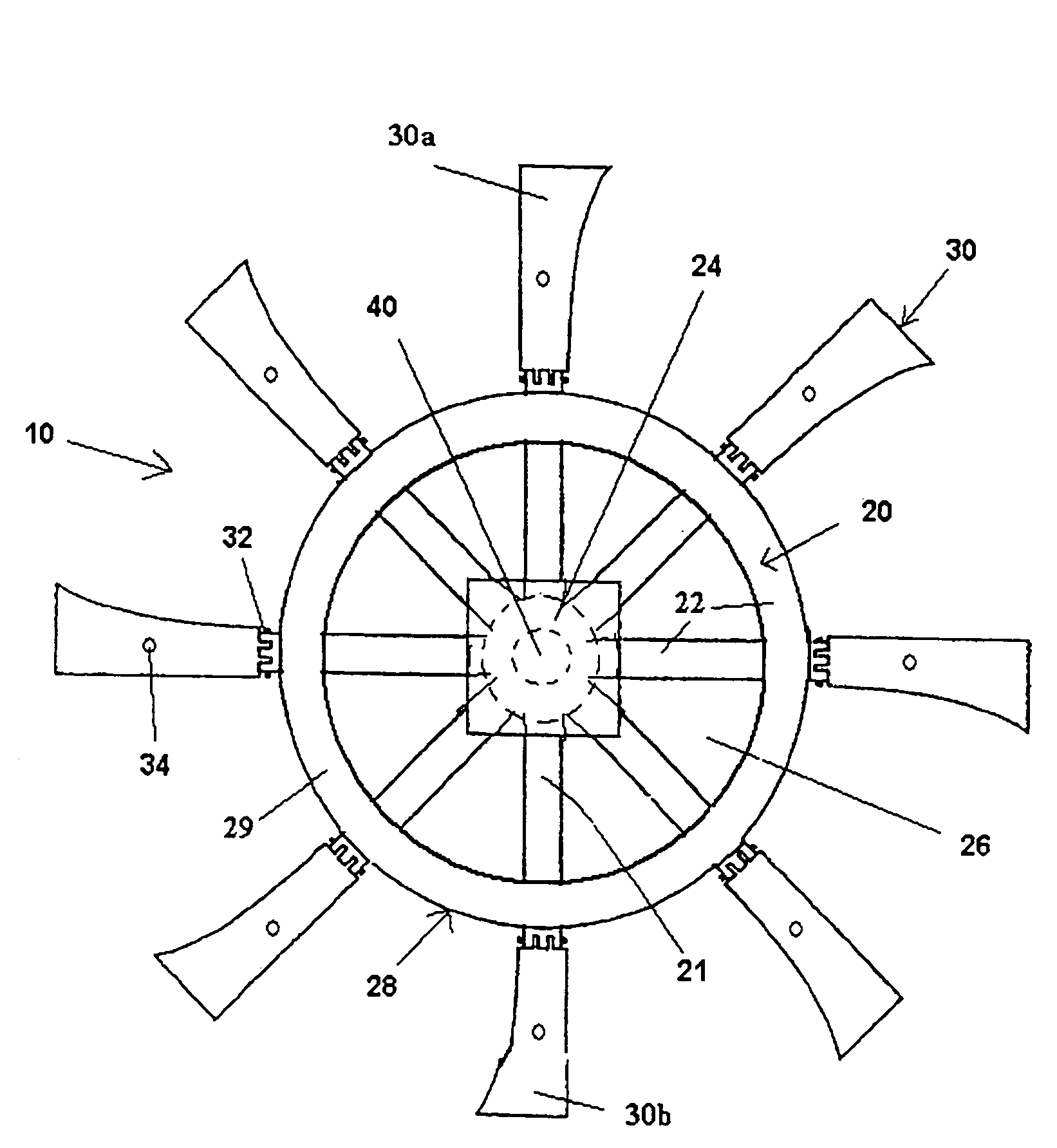
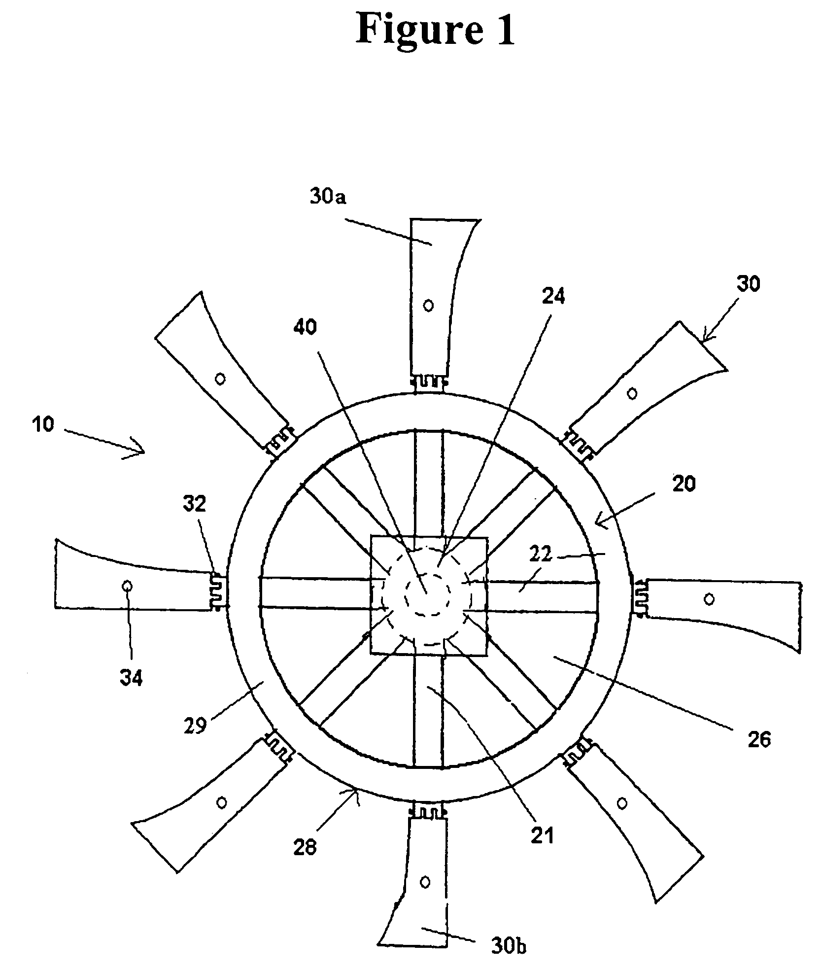
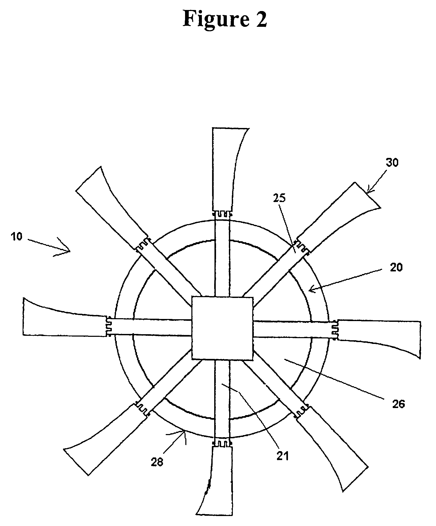
[0037]The present application relates to a wind turbine having improved features which allow it to generate power more economically than presently known wind turbines. The present turbine includes a rotor hub of increased diameter compared to current turbine rotor hubs, allowing wider blades to be attached to the hub. Such a hub also facilitates connecting the blades of the turbine via a hinged connection, which allows the blades to be retracted in a controlled fashion in order to regulate the rotational speed of the rotor and to protect the blades. This feature in particular is useful during extreme operating conditions such as high wind, dust storms, and hail storms. In addition, the shaft and rotor of the assembly are provided with a pivoting mechanism, allowing the assembly to assume an altered pitch in order to regulate the rotational speed of the rotor.

Definitions

[0038]As used herein, the following terms and variations thereof have the meanings given below, unless a different ...


PUM


Abstract

A wind turbine including an open hub, foldable blades attached to the rim of the hub, and a mechanism for tilting the turbine is disclosed.

Description

CROSS REFERENCE OF RELATED APPLICATION[0001]This application is a non-provisional application of a provision application having an application No. of 60 / 679,345, and a filing date of May 9, 2005.BACKGROUND OF THE PRESENT INVENTION[0002]1. Field of Invention[0003]The present invention relates to a turbine, and more particularly to a wind turbine comprising a rotor hub which has a peripheral guiding rim adapted for guiding a flow of air to a plurality of blades so as to maximize an efficiency of the wind turbine.[0004]2. Description of Related Arts[0005]Wind is the movement of air, which has mass, and when air is in motion it contains kinetic energy. A wind energy system converts the kinetic energy of wind into mechanical or electrical energy that can be harnessed for practical use. Mechanical energy harnessed by windmills, for example, can be used for tasks such as pumping water for a well.[0006]Wind energy systems which harness electrical energy are generally referred to as wind tur...

Claims


Application Information

Patent Timeline
Patent Type & Authority Patents(United States)
IPC IPC(8): F03D3/04
CPCF03D1/04F03D1/0666F05B2260/74Y02E10/721F05B2240/33F03D15/10Y02E10/72F03D1/0658F03D13/10
Inventor SOHN, CHESTER
Owner SOHN CHESTER
Why Eureka
Try Eureka